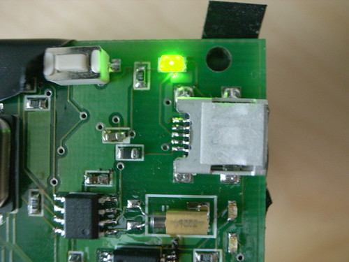
I dunno, I was staring at the Slow Messenger and the power LED — your typical grasshopper green — was so bright and just staring at me and kind of giving me a headache. And I thought..that’s not about slow. And I thought about the drowsy white “sleep” pulse of my PowerBook and I was, like..I need something like that on this device. A slow, sleepy, drowsy pulse. And maybe the pulse will change at different times of the day or something.
Lucky for me I had attached the LED to one of the timer/comparator signals on the ATMega32 in the design.

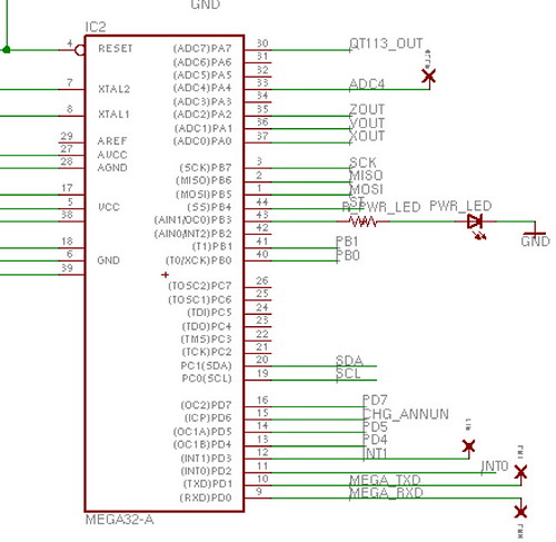
That signal — PB3? Over there on the left side of the Atmega32? That has an “alternate” use as an output for the timer/comparator circuit. That means that it will output a digital signal if you tell it to based on an internal counter equalling (comparing to) a value you specify, or when a timer is done counting up or down. So, by knowing things like how fast the chip is running (8 megahertz in my circuit) you can start to derive how often this signal will get turned on and off. Pretty soon you’re doing pulse-width modulation, something this MCU has built-in facilities for. With PWM you can make an LED think that the voltage being supplied to it is different values. If you change the PWM (and the apparent voltage to the LED) you can get it to dim to varying degrees. Or do a gooey, drozy pulse.
Here’s the code that will do this on an Atmega32. I’m having trouble getting it to work on the Atmega324 (which appears to be a replacement for the Atmega32), but I’ll get that straightened out soon enough..
#include <stdlib.h>

#include <avr/io.h>

#include <avr/interrupt.h>
#include <avr/pgmspace.h>
#include <util/delay.h>
#include "a2d.h"
#include "uart.h"
#include "avrlibdefs.h"
#include "avrlibtypes.h"
/* define CPU frequency in Mhz here if not defined in Makefile */
#ifndef F_CPU
#define F_CPU 8000000UL
#endif
static char mPwrLedLevel = 0;
static void incr_pwr_led(void);
ISR(SIG_OVERFLOW0) {
incr_pwr_led();
}
ISR(TIMER0_COMP_vect) {
incr_pwr_led();
}
static char aDirection;
static void
incr_pwr_led(void)
{
//TIMSK = 0x03;
if(mPwrLedLevel == 0x20) {
aDirection = 1;
}
if(mPwrLedLevel == 0xE0) {
aDirection = 0;
}
if(aDirection == 1) mPwrLedLevel++;
if(aDirection == 0) mPwrLedLevel--;
OCR0 = mPwrLedLevel;
}
int main(void)
{
sbi(DDRB, PB3);
PORTB |= (1<<PORTB3);
for(int j=0; j<30; j++)
_delay_ms(32);
cbi(PORTB, PB3);
for(int j=0; j<30; j++)
_delay_ms(32);
sbi(PORTB, PB3);
for(int j=0; j<30; j++)
_delay_ms(32);
sbi(PORTB, PB3);
for(int j=0; j<50; j++)
_delay_ms(32);
TCCR0 |= (1<<WGM00) | (1<<COM01) | (1<<CS02);
// TCCR0A |= (1<<CS02) | (0<<CS01) | (0<<CS00);
// TCCR0A |= (0<<WGM02) | (1<<WGM00);
// TCCR0A |= (1<<COM0A1) | (0<<COM0A0);
TCNT0 = 0x00;
sbi(TIMSK, TOIE0);
sei();
OCR0 = 0x10;
int j=0x00;
while(1==1) {
_delay_ms(32);
}
}
For the Atmega324 a bunch of registers and bit names in registers changed. This is all documented here:
http://www.atmel.com/dyn/resources/prod_documents/doc8001.pdf
I misread a bunch of it and kind of got a bit fouled up, but finally got it straight. It’s actually pretty simple once you get the registers figured out (things got split up because extra timers appeared and such.)
Basically you want to set up the PWM timer like this:
TCCR0A |= (1<<wgm00) | (1<<com0A1); //PWM Phase Correct, Clear OC0A on compare mach

TCCR0B |= (1<<cs02); // clk/256
TCNT0 = 0x00;
TIMSK0 |= (1<<toie0); // overflow interrupt enabled
OCR0A = 0x10; // start somewhere
Here’s a little CPP class that will run on the Atmega324p and slowly pulse an LED attached appropriately to PB3.
#include <avrlibdefs.h>

#include <avrlibtypes.h>

#include <stdint.h>

#include <stdio.h>
#include <util/delay.h>
#include <avr/io.h>
#include <avr/interrupt.h> // include interrupt support
#include "timer.h"
#ifdef __cplusplus
extern "C"{
//#include "a2d.h"
#include "timer.h"
#include "uart.h" // include uart function library
FILE * uart_str;
} //extern "C"
#endif
static uint8_t mGoLow;
void setup(void);
static void delay_1s(void);
static void delay_600ms(void);
static void delay_300ms(void);
static void incr_pwr_led(void);
static byte mPwrLedLevel = 0x00;
ISR(SIG_OVERFLOW0) {
incr_pwr_led();
}
ISR(TIMER0_COMPA_vect) {
incr_pwr_led();
}
ISR(INT0_vect) {
cli();
sei();
}
static void
delay_600ms(void)
{
uint8_t i;
for (i = 0; i < 60; i++)
_delay_ms(10);
}
static void
delay_300ms(void)
{
uint8_t i;
for (i = 0; i < 30; i++)
_delay_ms(10);
}
static void
delay_1s(void)
{
uint8_t i;
for (i = 0; i < 100; i++)
_delay_ms(10);
}
int main() {
setup();
}
static char aDirection;
static void
incr_pwr_led(void)
{
//TIMSK = 0x03;
if(mPwrLedLevel == 0x10) {
aDirection = 1;
}
if(mPwrLedLevel == 0xD0) {
aDirection = 0;
}
// printf("[[%d]]n", mPwrLedLevel);
if(aDirection == 1) mPwrLedLevel++;
if(aDirection == 0) mPwrLedLevel--;
OCR0A = mPwrLedLevel;
}
void setup()
{
uint16_t *base_addr;
uint16_t k;
float x_sum;
mGoLow = 0x00;
//uint16_t k;
sei();
MCUCR = (1<<ISC01);
MCUCR = (1<<ISC00);
// GICR = (1<<INT0);
sbi(DDRB, 3); // use PB3 as an output
PORTB=0x00;
sbi(PORTB, PB3); // PB3 high, on v04 is pwr led
//TCCR0 = 0x64; // prescaler and other stuff
TCCR0A |= (1<<WGM00) | (1<<COM0A1);//PWM Phase Correct, Clear OC0A on compare match
TCCR0B |= (1<<CS02); // clk/256
TCNT0 = 0x00;
TIMSK0 |= (1<<TOIE0); // overflow interrupt enabled
//sbi(TIMSK0, TOIE0); // overflow interrupt enabled
// TIMSK = 0x02; // overflow interrupt enabled
OCR0A = 0x10;
delay_1s();
cbi(PORTB, PB3);
while(true) {
if(mGoLow == 0x01) {
cbi(PORTB, PB3);
} else {
mGoLow = 0x00;
sbi(PORTB, PB3);
}
}
}
Technorati Tags: Near Future Laboratory, slowest instant messenger