Here in Barcelona, we continue fine tuning Quadrigram, with now a meticulous work on the coherence of pre-programmed modules the tool will provide to access, manipulate and visualize data flows. It also means some backstage cleaning and improvements of the engine that supports the visual programming language.
We have also been busy joining forces with our new friends at the user experience & data visualization studio Interactive Things. They have been mandated to produce visualization mobile phone network traffic and we do our best to provide the cleanest and more meaningful pieces of data. Their magic will be presented at Lift 12.
In the meantime, Yuji Yoshimura traveled to Helsingborg, Sweden to present at ENTER2012 a study of the visiting experiences at the Louvre Museum. His paper New tools for studying visitor behaviors in museums: a case study at the Louvre is the result of a collaboration between Universitat Pompeu Fabra, MIT SENSEable City Lab and us. It builds on the data we collected in 2010 to measure hyper-congestion phenomena in the busiest areas of the Louvre.
In Geneva, the week was focused on various projects. It was the last week of teaching at HEAD-Geneva this semester. Last Monday, I gave a course about innovation and usages and another one about design ethnography (which was actually made of students presentation). Tuesday was devoted to meetings in Saint Etienne (France) at Cité du Design, a quite big Design Center located in an old and beautiful manufacture. Then I (Nicolas) gave a presentation there about human-robots interaction (slides are on Slideshare). The rest of the week was spent in meetings with Lift speakers, students (time to discuss their masters thesis!) and watching video material for the current field study about head-mounted displays. The end of this project is pretty soon and we are currently working on the final presentation for the client.
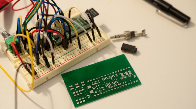
In Los Angeles, Julian was a busy-bee trying to get PCB’s fabricated for the Ear Freshener’s
I think going forward I should do a better job of talking around what we’re working on from a technical point of view, until such time as it’s okay to talk about what we’re doing from a principles, rituals and practices point of view. And, also — sometimes in the thick of a design-making-schematic-and-hot-air-baking fire-fight, I do something that I”ll likely have to do again, but without a good, thorough practice of writing things down to remember I, like..forget.
Here’s the thing. I’m making a little tiny audio device. It’s tiny and meant to be simple to use. Like Russell taught me — the thing about audio? You should be able to just turn it on and sound comes out.
I like that rule. That’s what radios used to do before all the knobs, settings, configuration preferences, long vertical scrollable lists and Internet connections fucked things up. You turn the little serrated rotary dial and *click* — radio sound. At worse? Static. But sound started. No swipes. No multi-finger gestures. No tyranny of the 10,000 hours of music & sound in the palm of your hand..and no idea what you want to hear.
There’s something lovely about that that is just pragmatic from an IxD and UX design point of view. I’m not being nostalgic.
So — translating this principle and making it active and not just a sweet, essentialist sounding statement into the guts of the things we’re making, I spent most of yesterday pondering how to make Ear Freshener exhibit and embody and be an exemplar of this design rule. Even to the point of saying, okay..no on-off switch.
Huh?
Yeah, well — the Ear Freshener has the advantage of being a plug-y thing. No speaker. It’s an intimate audio headphone thing. You’d only expect sound out of it when you plug in your headphones. Otherwise — it’s just a little thing that’s quite opaque. There’s only the tell-tale 3.5mm hole that indicates — audio/sound/plug-in-y-ness.
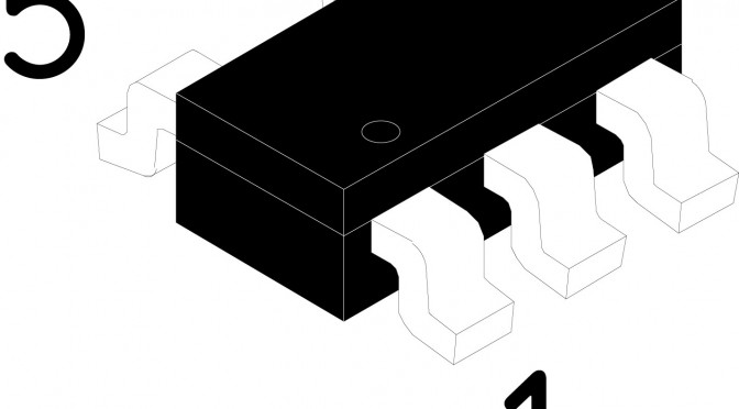
So — simple enough. I decided that plugging-in should equal sound-coming-out. That means that the plug action should turn the actual electronics on. In the world of audio connectors, CUI, Inc. is the go-to operation — along with what I’m sure is a thriving, teeming “ecosystem” of knock-off competitors who may even produce a superior product. They make all sorts of audio connectors for the world of audio devices. There’s a collection of them that have more than the three connectors that are necessary for a Tip Ring Sleeve style stereo audio signal, including the SJ-43614 which is a 3.5mm plug with four signals. The extra one switches from floating (not connected to anything) to ground (or the “sleeve” of the connector, which is normally connected to ground) when you plug a plug into it.
Brilliant. Something changes when you plug the plug into the SJ-43614. One of those signals on that connector gets shorted to the GND rail of the circuit.
Now..what to do with that state change in order to turn the whole circuit on and make sound come out of it with no fuss, no muss.
I pondered and scritched and screwed my face and looked for the answer somewhere on the ceiling over there. I thought of lots of overly-complicated things (as it turns out..in hindsight..) like using a low-power comparator to activate the chip-enable pin of the little 200mA step-up switching regulator I’m using so I can run the circuit off a single 1.5V battery cell.
In that over-designed scenario the NCP1402 step-up regulator is effectively the power supply for the circuit, which wants at least 3.0 volts to operate properly (and draws about 40mA). I can get an NCP1402 hard-wired to output 3.3v, although I may get the 5v version to have a bit more headroom with volume. In any case, this chip is fab cause you can take a little 1.5v cell and it’ll tune up the voltage. Of course, it’s not 100% efficient. Nominally, it’s about 80-ish% efficient at 40mA. So..you lose a little, but you can’t get something (5v) for nothing (1.5v) without giving up something in the trade.

NCP1402SN50T1 efficiency versus output current
So, I have a 1.5v battery of some sort which sits behind the NCP1402. The NCP1402 has an active high chip-enable (CE) pin that turns the chip on — effectively powering the rest of the Ear Freshener circuit. In my overly-complicated scenario, I figured I could use a comparator to sense when the 3.5mm plug had been plugged-into because that one switched pin would go from floating to ground. If I had a simple little 10k resistor between the positive 1.5v side of the battery, the comparator inputs could go on either side of that resistor, with the IN- of the comparator on the side of the resistor that would get shorted to ground when the plug is plugged in. And then the IN+ of the comparator would go on the side of the resistor that is connected directly to the positive side of the 1.5v battery. When the plug goes in, the IN- of the comparator goes to GND, the 10k resistor has a little, negligible-y minuscule current draw and the voltage difference between IN- and IN+ causes the output of the comparator to saturate to pretty close to IN+, or +1.5v. The NCP1402 chip enable would trigger (specs say anthing about 0.8v means “enable” and anything below 0.3v means “disable”) and the whole thing would turn on.

Click the image to expand it and make it easier to read. This is the lousy, over-designed circuit.
How convolutedly and moronically clever is that, especially when you stop to think (as I did, after proudly building the schematic) that you could just use that pin from the plug shorting to ground as a way to close the GND rail of the whole circuit. I mean..if you disconnect the NCP1402 from GND, it should turn off. Basically, it’d have no complete, closed, power supply circuit. It’s as if you pulled the battery out — or half of the battery out. Or ripped out the ground wire.
Anyway. It was clever to get all busy with a comparator and stuff. Simple’s better, though.

This is the simple, no-brainer one that eliminates the need for several additional components.
That’s it. I like the principle and I like even better the fact that I can translate a lovely little design principle into action — materialize it in a circuit that exhibits a fun little unassuming behavior. I can imagine this’d be a bit like wondering if the light stays on in the fridge after closing the door, you know?
So sound stops coming out, the circuit powers down and you no longer need an on-off switch. Stop listening? Turn off. So much nicer than long-press, id’nt it?
Why do I blog this? Cause I need to capture a bit more about the production of this little Ear Freshener-y gem.
Update
Here’s my update on the power circuit. I hope it works. I added two transistors in place of the comparator. The idea here is that the transistor on the right would switch the CE of the step-up switching regulator. When the base goes low — i.e. when the 3.5mm plug is plugged in — the switch opens and CE gets switched to roughly VBATT and enables the step-up regulator. For the transistor on the left, plugging in opens the transistor and VBATT gets connected to the step-up regulator and it, like..steps-up VBATT to VCC. When the plug gets pulled out and floats at VBATT, the two transistors saturate and are on. So on the right, CE is at Vce or effectively ground and shuts the step-up regulator off. The transistor on the left does similar and VBATT drops over R6 and VBATT_SWITCHED is at GND and there’s no longer any supply to step-up, even if the step-up regulator were enabled.
That’s the idea.
We’ll see. I haven’t computed the values for the discretes around the transistors as of yet.
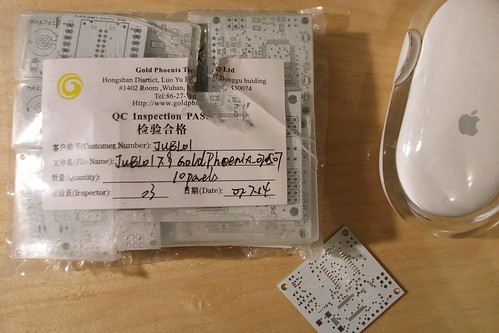
Related — I’ve just sent off the PCB to get fabricated. It’ll be a 2-off prototype. I’m using AP Circuits for the first time because my usual go-to guys Gold Phoenix are off for the Chinese New Year and I need to get this done for some building & testing next week.
But I think I mucked up the CAM data files I sent them, which appear to be slightly different from Gold Phoenix. They want other stuff, like the NC Tool list which I’ve never sent to Gold Phoenix. I guess we’ll see what they say.
Continue reading Sound Should Just Come Out Of It
So, I’ve been pretty happy sending printed circuit boards off to this Gold Phoenix operation in China. It feels global to do my manufacturing offshore and its certainly a heck of a lot cheaper than doing it onshore. Frankly, my budget is my pocket money and every penny counts. I’ve been even happier that I can do this stuff all on my own and learn just how these things are made. I mean, it’s one of those things I wish they had maybe taught us back in electrical engineering school, but maybe they thought it was too vocational. Anyway, I really haven’t used a drop of what I learned from back then, honestly. Maybe they taught me how to think or whatever. Who knows.
Anyway, I’ve been overwhelming myself with new projects because I can make my own boards, and being able to have multiple designs fit on one larger panel is really fueling the preposterous number of projects underway. I found out about Gold Phoenix through Nathan/Spark Fun‘s boardhouse batchpcb, which I’ve used in the past. I needed more boards done quicker and in greater quantity than made sense with batchpcb. Nathan never hid the fact that they’re an aggregator for Gold Phoenix, producing amazing prices for very small quantities if you could wait 15 or so days to get them back. For the quantities I needed (couple dozen) it made more sense to go directly to Gold Phoenix.
(You can read this as “Part II” of a review I did earlier of about four board houses.)
So, it’s the same drill to get your boards done, even easier in some regards, but much less hand-holding so you need to pack a reserve ‘chute the first time around. If you have a single design, you basically generate your Gerber‘s the same way you normally do. I even used the Spark Fun Electronics CAM file to generate the Gerber’s. SFE has a tutorial right here for using Eagle to generate Gerber’s. I’ll repeat a few things here.
The Gerber‘s are basically (barely) human readable, but mostly machine readable, text files that describe what goes where on your PCB. For instance, from where to where a bit of copper should go, where a hole goes and how big its diameter. That sort of thing. So, it’s the physical description of your layout, one file for each layer of the board. I’ve only done two layer boards. That is, two layers of copper. Which means that I have six Gerber files plus a drill file. The Gerber’s are one each that describes the top and bottom copper, one each for the top and bottom solder mask, one each for the top and bottom silk screen. Finally, there’s this “NC drill file” used to describe the drilled holes (vias, mounting holes I poke through the board, any through-hole components, etc.) So, that’s six Gerber files and a drill file. You zip those up into a .zip file.
Eagle spits these out when you run the CAM processor using the SFE-Special.cam file that Spark Fun Electronics graciously makes available. It basically does what you need to be done.
Top and bottom silkscreen is a little tricky because it actually pulls the silkscreen from two special layers (_tsilk and _bsilk) that are created by another script (or “ULP” for user library program) also provided by Spark Fun. This other script is called silk_gen.ulp. What it does is make your silk screen drawings a bit “thicker” than the default thickness created by Eagle. It actually copies the geometry and patterns from the normal (by convention) layers that are used to draw paint (silk screened, but I doubt the process involves and actual silk screen nowadays) on the boards. Those layers, best as I can tell, are tPlace and bPlace (top and bottom placement marks for components.) If you run this ULP you’ll see all the tPlace and bPlace redrawn in a different color — and if you check your layers you’ll notice that two more appear in the “Display” pane of Eagle. What happened is that everything in tPlace and bPlace is drawn thicker in _tsilk and _bsilk. You’ll see any text thickened, etc. Evidently, this is necessary for the actual process of applying the silk screen paint to the board.
[ad#ad-4]
The files that you need for production are generated by the CAM Processor. These are:
Top Copper (CMP)
Bottom Copper (SOL)
Top Soldermask (STC)
Bottom Soldermask (STS)
Top Silkscreen (PLC)
Bottom Silkscreen (PLS)
Drill File (DRD)
While we’re talking about layer mishegoss, you’ll notice that there’s also the Dimension layer that looks like it’ll be drawn in paint, but that layer’s geometry does not get drawn as paint — I’m pretty sure it’s used to define the boundaries of the board as the board will be cut out of the panel. I’m not 100% sure how the process works, but empirically — based on runs I’ve done — this’ll allow you to shape the board into whatever shape you need. (See below, some of the boards have slightly rounded edges, and one even has a bit cut out where a battery can fit.) What gets drawn in paint and what doesn’t is determined largely by convention. These “silk” layers are handled by the CAM Processor as layers to be drawn in paint by putting the geometry in the top or bottom silk Gerber files. Whatever geometry you put in that file will get drawn as silk. If you mess up and put your copper geometry in there, they all of your traces and pads and such all will get drawn as paint, which is pretty cool, but something mostly people don’t want. Essentially you’re giving whatever hulking steampunk machine is on the other ed of this instructions on where to lay copper and where to lay paint and where to drill holes and where to cut PCB.
Okay, so — you’re probably better off following Spark Fun’s tutorial, because that’s just a brief summary of the drill you’ll go through. I’m just trying to get to the point of seven Gerber files zipped up into a zip file.
For the Gold Phoenix run, you just email that zip file to their guy Shane in Toronto with a description of what you want. I’ve been taking advantage of these summer specials they’ve been offering. It’s a menu of options such as how big a panel you want your parts cut from? What weight of copper? How thick should the boards be? What color soldermask? What’s your thinnest trace, etc.
For example, for this batch of parts, my order looked like this:

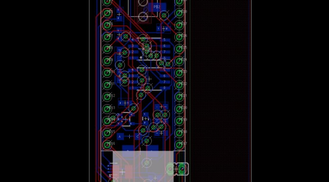
That’s about it. No web form. No drop-down box. My shipping address? I put it in the PayPal form when I paid my $159. I had multiple boards that I put in the layout — those six separate boards? So I had to fork over an extra $30 as a tax for making their lives a little bit harder — fine with me! I get five projects taken care of at once. My board file looked like this (it’s like a board of boards, really):
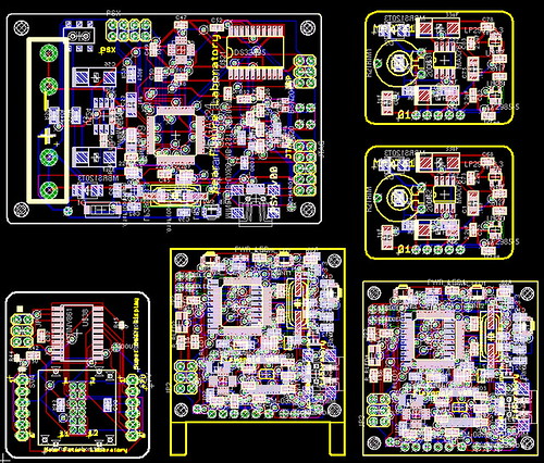
This was just a board, no schematic. Each one of those individual parts there? They were each designed separately, on their own the usual way. (Create the schematic in Eagle, create a board from the schematic, place parts, route, etc.)
This board of boards was created as a new board design — just a board, not a board and schematic. This is the board design I’ll use to generate Gerbers and drill file for the final thing I send to Gold Phoenix. But, first you need to put all the individual solo-created boards together on this blank board. (I think this is basically what happens when people do what they call panelize or panelizing, but I might be wrong.) You’re basically going to create one board with lots of smaller boards on it. The outlines for each smaller board are what the Gold Phoenix people will use when they cut up the larger board into smaller pieces. They’ll also do the “step and repeat” process of filling up the larger panel with multiple instances of the one board that contains lots of little individual boards.
This is like a three layer Russian Doll. You have your individual boards for some little design projects you’re working on. Then you have this board that contains each of those little board designs, placed thusly so that there’s a little space between them and they don’t overlap and maybe even consume a rectangular shape, etc. Then there’s the “panel” which is the sheet of material that will become a big sold piece of lots of little designs.
When I got the boards done individually, I turned on all the layers in Eagle, and used Eagle’s “cut” command (confusing..it basically means copy) after selecting everything and placed the individual board on my one larger mothership board. I did that for each design. (One of the designs I put on twice to make the basic outline of the whole thing roughly rectangular. I just sort of assumed that that would make more efficient use of space for the step-and-repeat process of duplicating this design across the larger panel. Todbot thinks that they maybe adjusted the placement of my individual pieces because, by my calculations, I should’ve gotten 9 of each piece and instead I got 10. Anyway, 10 is better than 9.)
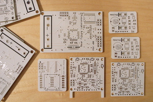
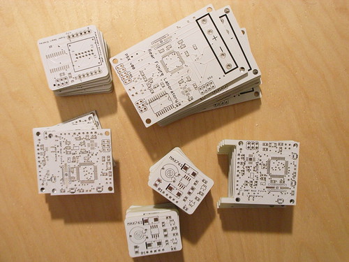
So, what Gold Phoenix ends up doing is taking this one board of boards and making it fit in 1000 square centimeters as many times as they can. This is why I get many copies of each board, 10 in fact of each board because my board of boards can fit 10 times in 1000 square centimeters because its just about 100 cm square (120 actually on my side, but, like Tod said, they must’ve tightened up my board of boards on their end.) They saved me a lot of trouble this way. Rather than me having to make a board of boards 1000 cm square, they do it for me based on my one board of boards template.
This is what showed up in the FedEx pouch from China 9 Days Later (coulda been sooner if I paid a little extra for extra fast turn-around.)
I don’t think you can beat that for quality, quantity, time and price with any of the other four or five places I’ve tried. One place was $33 + $40 shipping and handling (scam) for one tiny board, no soldermask (yeech..) no silk, 5 day turn-around. Like..hello?
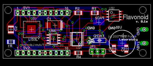
So, I’m at the point with the Flavonoid project that I need to start getting printed circuit boards made. (The printed circuit board includes an accelerometer, a real-time clock, touch sensor, and a bit of EEPROM memory, if you want to know.) A fair bit of the break was spent schooling up on Eagle, doing layouts, making mistakes and that sort of thing. (It’s remarkably full-featured for a free product and, despite a few quirks, does what it says it will do. Plenty of activity in the forums and help is quick to come when I’ve gotten in trouble.)As I closed in on a design I thought was close enough to gold to send off, I started poking around various forums to find out what operation might be suitable for small (1-10 piece) runs.
It turns out that most of the places you’ll hear about won’t do fewer than 5 pieces, and they’ll charge you for it, too. By way of example, I considered trying Advanced Circuits as the Spark Fun FAQ suggests them if you’re in a pinch for time. It’d have to be more than a side-project financed with my own wallet to use them, but maybe they’re better for big projects. (I compare them to the other two board houses near the end of this post.)
The one great exception is Batch PCB, the operation started up by the Spark Fun guys. They’ll do single pieces for, like..$2.50 per square inch. In my limited experience, that’s a great deal. In exchange, you’ll have to wait a bit longer to get your boards back — I think they’ve worked something out with their guy in China so that the numbers work out to get that kind of pricing.
The two places I’m trying are Batch PCB and PCB Fab Express. I picked PCB Fab Express because they had something they refer to as a special for prototypes, but it’s still pretty expensive (but less expensive than other places that’ll turn something around in under a week). I’m doing this so I know what my options are in the future. I can imagine times when waiting a couple of weeks is fine, and other times when I’d like to have something in a few days.
Batch PCB
This is Spark Fun‘s boardhouse operation, which I’d generally just use without even thinking twice, and I have, basically. The one small thing that makes it not necessarily a slam-dunk is the turn-around, which will be at least 10 days. But, that’s probably just fine, except sometimes I feel anxious. But, you know — it’s not like I have customers waiting for product or anything..just me. So, that aside, the Spark Fun guys are friends of the cause and so I support them whenever possible. What you’ll get are 2-layer (seems like they’re doing up to 4 now) boards with pretty much everything. No need to count vias or stuff. Silkscreen on both sides. 8 mil wires and a recommended 10 mils spacing. You can order one board if you want, which is fantastic (as opposed to most other places that make you order 5 of something for which you need only one, or which isn’t 100% yet, so you may end up getting 5 drinks coasters for your $100.) You can put more than one design in your board and just score the two, which can save you some trouble. They have one thing that most places don’t even think to provide — a simple, short-and-sweet Eagle tutorial on preparing your Gerbers. They have a hopped-up forum, where answers to your questions come back pretty lickity-split. Their DRC bot sends you a decent design review summary within a few minutes of uploading your Gerber .zip file (I’m still waiting to get back the DRC from PCB Fab Express, which I sent in a couple of hours ago.)
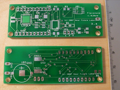
Flavonoid PCB’s just arrived from BatchPCB.com
All-in-all, this is the place to go if you can wait a couple of weeks for your parts. The PCBs you see above were sent in on December 28, and arrived on January 18. Considering generally delays during the holidays, and that Boulder (where those guys are) got socked in by a nasty blizzard, I’d say that’s satisfactory. Total cost for four boards with express shipping was $49.92 Compare to $82.95 for PCB Fab Express, five boards, five days, super-saver shipping. If you’re in a rush or just hopped-up and heads-down in a project, I’d guess the extra $30 is nominal. Note that PCB Fab Express won’t silk screen the back of the board, but that’s not such a big deal in most situations, particularly for prototyping.
One thing I noticed about the boards is that they’re not all 100% the same footprint. By this I mean that the way they were cut out of the larger panel (with probably lots of other people’s boards on it) resulted in slightly different dimensions. I mean, slightly. If you put the boards together like a sticks of gum in a pack, you can tell that some are slightly larger/smaller along the various dimensions. One even seemed slightly curved. This could be an issue if the packaging in which these boards are placed has critical sizing issues. But, it’s ever so slight — nothing that a fine file couldn’t smooth out, if it even caused a problem. (I’m talking about something that’s noticeable if you eyeball it, and measuring, it seems to be about 1mm or less discrepency in size.)
Summary: BatchPCB.com, four boards, silk screen on both sides, 14 business days turn-around, with a blizzard interfering, $49.92 with shipping.
Note that BatchPCB turn-arounds get shorter the more work they do as a company. Presumably, they are able to fill panels sooner and ship whatever minimums they need to their guy in China. Now (January 19) they say they’ll panelize a board in four days, so the turn-around is likely closer to 10 days or thereabouts. That’s fantastic. I also found BatchPCB to be much more “user-friendly”, as is generally the way with the Spark Fun team. (Their tutorials are excellent, particularly the one on does and don’ts for prototyping, all based on real experiences. Don’t forget their surface mount technology tutorials, too, found here. I had two situations where I needed to cancel an order I had submitted. Fortunately, it hadn’t gone too far into the cycle and they could delete the order. Their DRC bot is also quick and provides some useful graphics to give you a sanity check about what precisely you’re submitting.
PCB Fab Express
Okay, this operation seemed a little weird from the get-go, mostly because I got a call about 20 minutes after I created an account. (That sort of bothers me.) But, I talked to the sales guy and was assured that when I submitted by Gerber zip file, I’d get a design review check done and an email back. I submitted my Gerber zip file and must’ve misread something somewhere because my order was put “in process.” The board, my fault completely, had a ground plane copper pour that seemed okay, but I noticed that there were these friggin’ vias going through it. It was just all messed up, but I fixed it in about 3 minutes. Unfortunately, if they even had a DRC, it didn’t catch this (not sure it would’ve, even though it basically meant that nets that shouldn’t connect were connected.)
I tried to cancel it (calls and emails) but probably between a mix of my not being as attentive to what I clicked on and the holidays, there was no way to get the order out. I think there’s a problem in the Gerber I sent them, and I’m a bit surprised I didn’t get a DRC email or anything, but..well..I guess chalk that up to experience. (Update — it seems fine after eyeballing the boards I got.) Their prices are a bit more reasonable than other operations for the turn-around — 5 boards, 5 days, $82.95 with tax and “super saver” shipping. They’ll do a finer line spacing than is typical (6 mils). The largest drill hole they’ll do is 246 mils plated, which is fine, only sometimes a mounting hole might be larger, possibly. They have some restrictions on the average number of holes per square inch, which could be annoying if there are lots of vias or whatever. Two-layers, but no silkscreen on the bottom, which one can typically live with for a prototype.The boards just came in, which is exciting. The problem I thought I was going to have didn’t appear for some reason. Unfortunately, I over-wrote the board file from Eagle and so I can’t double-check what I sent them. (I could look at the Gerber’s, though.)
I don’t have all the parts yet, but just a cursory look-see and I thought of a few notes to think about for any redesign.
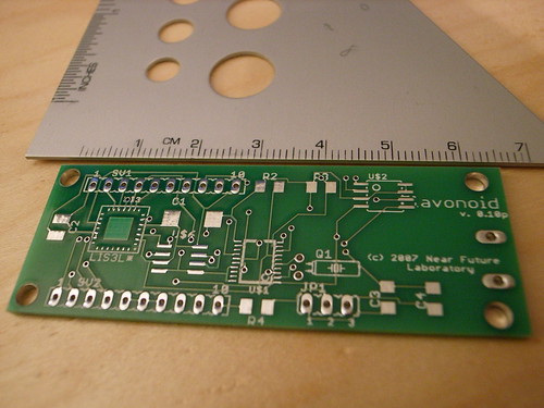
PCB Prototype Recto from PCB Fab Express 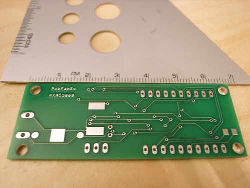
PCB Prototype Verso from PCB Fab Express. Notice there’s no silkscreen on the bottom.* First, some of the vias are unnervingly close to the pins of the DS1306. I’ll look for that in the future and put in a via keepout or something.
* Second, the crystal for the RTC I pulled from the crystal library. The pads for the package aren’t much bigger than a via, and there’s not much of a pad to speak of on the thru-hole. It might be just as well to find an SMT pad for it, or perhaps there’s a package in the crystal library for a surface-mount device.
* The mounting pin for the coin cell battery holder on the back is a bit close to the VBAT pad I put back there. I’m not sure if that mounting pin is connected to anything electrical in the coin cell holder, but I need to check just to be sure.
Summary: Quick turn-around. No hand-holding despite getting a sales call and promise of an email once I submitted. $82.59 with shipping for 5 boards, $16.52 per board, $6.19 per square inch. They took normal Gerber’s RS274X. I used the CAM processor user language program that Spark Fun provides for Eagle in their tutorial.
Advanced Circuits
Expensive and no real reasonable hobbyist pricing for a prototype option. This is probably “okay” for some situations, but certainly not for a hobbyist who’s just looking to get some boards done. No fault, no blame. Just thought I’d add it in since I went through the trouble of checking them out, but I won’t order from them.For comparision, I got a quote from Advanced Circuits for my test case — this Flavonoid PCB that you see above. For a “prototype” run, five boards in 3 days (the longest possible turn-around), it was $47 per board, or $235 without shipping. Their best value deal is 2 days, $57 per board. One day is $61 per board, and same day is $117 per board. Their production pricing — 50 units, say — is $5.86 per board in 2 weeks, or $7.57 a board in 3 days. So, roughly speaking, BatchPCB (described below) is priced in the same ballpark as Advanced Circuits’ production prices, even at single units. My BatchPCB boards came in 2 weeks and cost $7.50 a board ($2.50 per square inch, rounded up.)
Conclusion It’s hard for me to think why I would not use BatchPCB unless I really needed boards quicker than two weeks. If I need something in under a week, I’d go with PCB Fab Express. And, if I really am in some kind of project where I need dozens of printed circuit boards, I’d almost certainly go with BatchPCB — it’s just the best value.
If anyone has any suggestions of other board houses, please drop a line.
Update! I’ve been using Gold Phoenix when I need more boards as soon as possible — under a week. I haven’t completely run the numbers, but it’s pretty clear that for more than 10 boards or so, they’re the place to go to. If I need just singles of boards and can wait, I’ll use BatchPCB. I have a review of Gold Phoenix here.
For $89 (special summer deal pricing) you can get 1000 sq centimeters of PCB. When I put six designs on this size, I got 10 of each back. That’s 60 total boards. I paid extra to have some special features like white soldermask and black silkscreen and a $30 tax for multiple designs. Still, it seems like a great deal. Turn-around was under about 12 days.