I’m working on a project that needs a real-time clock, and so I thought I’d learn how to use one by interfacing it with an Arduino. Ultimately, it will interface with another AVR, but the Arduino is great for just prototyping the design, to make sure I really know how to work with the device.
I chose the Maxim DS1306 because it is an SPI compatible device, meaning I can just throw it on an SPI bus along with anything else. It’s also register based, so setting the time or reading the time is a fairly simple affair — you just read or write the appropriate register. The DS1306 has a sibling, the DS1305. Near as I can tell, the major differences are the existence of a 1Hz interrupt-drivable heartbeat on the DS1306.
The device also has a nice range of options for backup power, and keeping time even when primary power is cut off. I can use nothing and just loose the time, or I can hook up a 3V lithium battery to VBAT, or a 3V rechargeable, or a super capacitor. The last two options can be trickle-charged by the DS1306 while it is on primary power, so essentially, for most practical cases, the device will always keep the time, even when disconnected from primary power. It can even continue to generate an alarm (see below) while off primary power.
If you need a simple heartbeat, the DS1306 can provide an open-drain 1Hz signal that’s also suitable for driving an interrupt pin. It also provides a 32.768kHz signal that could be used similarly (the same frequency as the crystal used to drive the DS1306.)
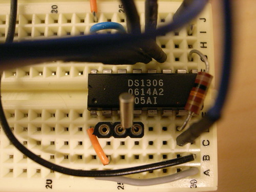
The only real external components you’ll need for this are a 32.768 kHz crystal (pretty standard) and possibly a couple of pull-up resistors and some kind of battery (rechargeable or a simple lithium coin cell) or a super capacitor as back up power. Or, if you go without the backup power, just ground VCC2 and VBAT, as per the specification sheet.
Schematic
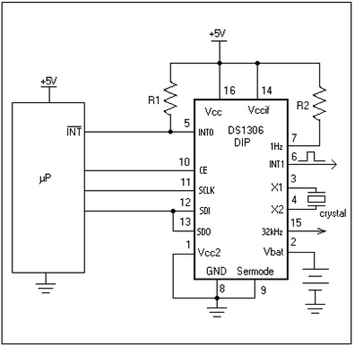
Easy-peasy. If you don’t plan on using INT0 for an alarm and/or don’t plan on using the 1Hz pulse you can leave those disconnected and you won’t need the pull-up resistors. (I used a 10K Ohm resistor.) The spec sheet for the DS1306 will tell you this, but you should tie VBAT to ground if you’re not using it. There’s a whole section on how to deal with VCC2 and VBAT depending on whether you actually have a backup supply, use a fixed battery, rechargeable or a super-capacitor, and how you charge the chargeable stuff. Read it carefully.
Programming
The device uses the SPI bs to communicate, and does so in SPI Mode 1, which means that the clock polarity is such that the leading edge is rising and the trailing edge is falling. (SPI has four modes, numbered 0-3, with all the combinations of clock polarity and clock phase. The device you’re using should specify either the mode or say something about the particular clock polarity or clock phase, and then you need to adjust the SPCR register appropriately. It’s simple, but a nuisance and probably the first thing you should check if something isn’t working correctly.) But, the clock phase is such that the leading edge is when the data is setup, and the trailing edge is when the data is sampled. The clock phase may seem “opposite” of convention, but it’s just another way of doing business. (In fact, if you look in the ATMega8 specifications — or any of the Atmel microcontrollers that support Serial Peripheral Interface – you’ll find that there are four SPI modes, with all the combinations of clock phase and clock polarity.) It’s just that the DS1306 expects the clock phase to sample on the trailing edge. How do I know this? The DS1306 specification document says so in its section on the Serial Peripheral Interface. (Woe is me for not reading the document thoroughly the first time I tried to use it – I didn’t even think that it might operate in a different SPI mode until a couple of hours of debugging finally lead me there..)
So, our set up of the ATMega8’s SPI interface has to be such that it’s ready to operate in the right mode. This little code idiom will do it:
  // SPI Enable (SPE) to one
  // Master/Slave Select (MSTR) to one turns the ATMega8 into the master
  // Clock Phase (CPHA) set to 1 means sample on the trailing edge
  // sample on trailing edge of clk for the DS1306
  SPCR = (1<<SPE)|(1<<MSTR)|(1<<CPHA);
  clr=SPSR;
  clr=SPDR;
Check the ATMega8 spec for more details about these registers.
(Parenthetically, I’ve pretty much got to the point where I have a bunch of devices on the SPI bus, and some of them require different modes. I’ve abstracted all of this functionality into read_register and write_register functions that accept a host of parameters, including what the clock phase and such all should be.)
What you do to program the DS1306 is basically write to and read from the registers. The registers hold the current time, the alarm settings, a number of control bits, and a small, 96 byte scratchpad of user RAM that you can read and write for your own purpose.
Each of the registers has it’s own read from and write to address, meaning each register has two addresses — one you use to read from the register, and one you use to write to the register. If you want to set the current day of the week, you’d write a value to the register at address 0x83. If you wanted to find out the current seconds, you’d read from the register at address 0x00.
Here’s the entire register table.
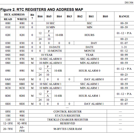
The control register manages enabling the two alarms, enabling the 1Hz heart beat output, and turning on or off the write protection, if you want to prevent any accidental writing of the registers. If you want to do a basic initialization of the device, the first thing you’d do is probably write 0x04, which would enabling writing registers, turn the heart beat on, and disable both alarms. Then you’d set the time by writing the the second, minute, hour and day of week registers, at which point the device would start keeping time. (Setting the right time initially requires getting the right time somehow – presumably through some sort of interface with the time keeping mothership or by setting it manually.)
BCD Time Data
All the time is stored in these registers in binary coded decimal (BCD), which is a data format appropriate for storing decimal numbers in a binary register. Decimal, of course, are numbers between 0-9. As is the case with time and date data, all the numbers there are decimal, too. So, storing this information as BCD makes sense — you don’t have to do any conversions from hexidecimal to a suitable display format. In other words, converting 0x0A to a number that represents seconds is avoided — the digit to be represented is what is stored in the register.
BCD stores each digit in half a byte (or a nibble, or 4 bits). Now, with 4 bits, you can represent any integer between 0-15 (or 0x00-0x0F in hexadecimal.) With BCD, the only “legal” integers are 0-9 (or 0x00-0x09 in hexadecimal). By convention, the other numbers are just ignored, or treated as illegal.
The DS1306 plays the same game. So, when you want to set the seconds to 45, you’d write 0x45 to the register at 0x80. If you wanted to set the hour to 8, you’d write 0x08 to the register at 0x82. Funny thing about hours to note is that you can either track in 24 hour time or the AM/PM variety. It’s up to you, but you need to set your register appropriate. It gets just a little bit more complicated with AM/PM time — read the spec for details on how to deal with that.
Alarms
The great thing about this RTC is that you can set a real-time alarm. Actually, the device supports two alarms in the form of the INT0 (active low) and INT1 pins. These pins are suitable for generating an signal on a microcontroller interrupt pin. (INT0 is active low, and open drain, so you’ll need to tie a 10K resistor or something from pin 5 to VCC1 to get a suitable signal to the microcontroller.)
Each alarm is set through four registers, one each for seconds, minutes, hours and day of week. The registers are used to match against the current time. In order to set up an alarm, you’ll need to set these registers to the time and day of the week you want the alarm to occur. Or, you can use the special mask bits, bit 7 of each register, to indicate a kind of catch-all. For instance, setting the mask bit in the minutes register indicates “all” minutes for the specified second, hour and day of week. Or, you could use the mask bit to have an alarm occur every minute, by setting the seconds register to 0x00, and setting the mask bit of all the other registers.
I mentioned the two alarms on the DS1306. Well, it turns out that INT1 is really only available when the device is powered by VCC2 (the backup supply) or VBAT (the battery supply). The other, the active-low interrupt 0 output INT0, is available when the device is powered by by VCC2, VBAT or VCC1 (the primary supply.) So, I guess you can have a special alarm that occurs when the device is running on the battery, or maybe this was an electrical design issue – INT1 isn’t open-drain, so it’s driven by VBAT or VCC2, which is something to keep in mind.
Here’s the Wiring/Arduino code to work with the DS1306 on the ATMega8, not the ATMega168 which is what the modern Arduinos use as their microcontroller. You’ll need to double-check which pins you’re hooked up to if you’re using another microcontroller.
Scroll down below to find the code for the modern Arduino’ss
This code sets the device up, and starts an alarm at 0 seconds, and then every 15 seconds thereafter. The alarm is the INT0 active low one on pin 5 of the DIP package. You’ll need to tie a pull-up resistor from that pin to VDD, or pin 9, and then tie a bit of hook-up wire from pin 5 to Arduino digital pin 3 (which is INT1 on the ATmega8).
You can also download the ATMega8 code here.
// ATMega8 Code
// ATMega8 Code
#define DATAOUT 11 //MOSI
#define DATAIN  12 //MISO
#define SPICLOCK  13 //sck
#define RTC_CHIPSELECT 7 // chip select (ss/ce) for RTC, active high
#define LED 10

byte clr;
char spi_transfer(volatile char data)
{
  /*
  Writing to the SPDR register begins an SPI transaction
   */
  SPDR = data;
  /*
  Loop right here until the transaction is complete. the SPIF bit is
   the SPI Interrupt Flag. When interrupts are enabled, and the
   SPIE bit is set enabling SPI interrupts, this bit will set when
   the transaction is finished.
   */
  while (!(SPSR & (1<<spif)))
  {
  };
  // received data appears in the SPDR register
  return SPDR;
}

void setup()
{
  char in_byte;
  clr = 0;
  in_byte = clr;
  Serial.begin(9600);
  // set direction of pins
  pinMode(LED, OUTPUT);
  pinMode(DATAOUT, OUTPUT);
  pinMode(DATAIN, INPUT);
  pinMode(SPICLOCK,OUTPUT);
  pinMode(RTC_CHIPSELECT,OUTPUT);
  digitalWrite(RTC_CHIPSELECT,LOW); //disable RTC


  // set up the RTC by enabling the oscillator, disabling the write protect in the control register,
  // enabling AIE0 and AIE1 and the 1HZ Output
  // 0x8F to 00000111 = 0x03
  // EOSC Active Low
  // WP Active High, so turn it off
  write_rtc_register(0x8F, 0x01|0x02|0x04);

  // little sanity checks
  in_byte = read_rtc_register(0x0F);
  Serial.print("CTRL REG [");
  Serial.print(in_byte, HEX);
  Serial.println("]");
  delay(10);

  in_byte = read_rtc_register(0x10);
  Serial.print("STATUS REG [");
  Serial.print(in_byte, BIN);
  Serial.println("]");

  // set up both alarms at 00 seconds?
  write_rtc_register(0x87,0x00);
  // mask all the other registers
  write_rtc_register(0x88,0x80);
  write_rtc_register(0x89,0x80);
  write_rtc_register(0x8A,0x80);

  write_rtc_register(0x8B,0x00);
  write_rtc_register(0x8C,0x80);
  write_rtc_register(0x8D,0x80);
  write_rtc_register(0x8E,0x80);

  in_byte = read_rtc_register(0x06);
  Serial.print("YEAR [");
  Serial.print(in_byte, HEX);
  Serial.println("]");

  in_byte = read_rtc_register(0x05);
  Serial.print("MONTH [");
  Serial.print(in_byte, HEX);
  Serial.println("]");

  // enable INT0, PORTD Bit 2 on the Atmega 8
  // we'll attach the 1HZ signal from the 1306, pin 7
  // or we can attach the active low interrupt output (pin 5 on the DS1306 DIP package)
  // to digital pin 3 on the Arduino (INT1 on the ATmega8)
  // I just picked INT1 arbitrarily - I think you could use any of the interrupts, so long as it
  // wasn't already being used by some other part of the Arduino.
  // cf. http://www.arduino.cc/en/Hacking/PinMapping?from=Main.PinMapping
  Serial.println(GICR, HEX);
  // enagle INT1 in the global interrupt control register
  GICR = (1<<int1);
  Serial.println(GICR, HEX);

  //Set the Interrupt Sense Control 1 Bit 1 and Bit 0
  //in the MCU control register
  //So that a falling edge of INT1 generates an interrupt request
  MCUCR = (1<<isc01);
  MCUCR = (0<<isc00);

  digitalWrite(LED, HIGH);

}

// can't really share variables unless they're declared
// "volatile", otherwise, they'll be set here, then popped
// back to their values before the interrupt handler was called
ISR(INT1_vect) {
  //signal that we have an interrupt
  //turn on the LED
  byte a;

  digitalWrite(LED, HIGH);
  // writing or reading from the DS1306 registers resets the alarm
  // so as to cause an alarm every 15 seconds.
  a = read_rtc_register(0x07);
  if(a == 0x00) {
    write_rtc_register(0x87,0x15);
  }
  if(a == 0x15) write_rtc_register(0x87,0x30);
  if(a == 0x30) write_rtc_register(0x87,0x45);
  if(a == 0x45) write_rtc_register(0x87,0x00);

  // every minute Ñ set bit 7, the mask bit, to 1
  write_rtc_register(0x88,0x80);
  // every hour
  write_rtc_register(0x89,0x80);
  // every day of the week
  write_rtc_register(0x8A,0x80);

}

void write_rtc_register(char register_name, byte data) {
  write_register(register_name, data, RTC_CHIPSELECT, HIGH, true, true);
}

char read_rtc_register(char register_name) {
  return read_register(register_name, RTC_CHIPSELECT, HIGH, false, true);
}

// reads a register
char read_register(char register_name, byte cs_pin, byte cs_active_level, boolean read_high, boolean cpha_trailing)
{
  char in_byte;
  if(cpha_trailing) {
    SPCR = (1<<spe)|(1<<mstr)|(1<<cpha)|(0<<spr1)|(0<<spr0);
  }
  else {
    SPCR = (1<<spe)|(1<<mstr)|(0<<cpha)|(0<<spr1)|(0<<spr0);
  }
  clr = SPCR;
  clr = SPDR;
  if(read_high) {
    // need to set bit 7 to indicate a read for the slave device
    register_name |= 128;
  }
  else {
    // if read low, means A7 bit should be cleared when reading for the slave device
    register_name &= 127;
  }
  // SS is active low
  digitalWrite(cs_pin, cs_active_level);
  // send the address of the register we want to read first
  spi_transfer(register_name);
  // send nothing, but here's when the device sends back the register's value as an 8 bit byte
  in_byte = spi_transfer(0);
  // deselect the device..
  if(cs_active_level == HIGH) {
    digitalWrite(cs_pin, LOW);
  }
  else {
    digitalWrite(cs_pin, HIGH);
  }
  return in_byte;
}


// write to a register
// write_high if true indicates set A7 bit to 1 during a write
void write_register(char register_name, byte data, byte cs_pin, byte cs_active_level, boolean write_high, boolean cpha_trailing)
{
  if(cpha_trailing) {
    SPCR = (1<<spe)|(1<<mstr)|(1<<cpha)|(0<<spr1)|(0<<spr0);
  }
  else {
    SPCR = (1<<spe)|(1<<mstr)|(0<<cpha)|(0<<spr1)|(0<<spr0);
  }
  clr=SPCR;
  clr=SPDR;
  // char in_byte;
  if(write_high) {
    // set A7 bit to 1 during a write for this device
    register_name |= 128;
  }
  else {
    // clear bit 7 to indicate we're doing a write for this device
    register_name &= 127;
  }
  // SS is active low
  digitalWrite(cs_pin, cs_active_level);
  // send the address of the register we want to write
  spi_transfer(register_name);
  // send the data we're writing
  spi_transfer(data);
  if(cs_active_level == HIGH) {
    digitalWrite(cs_pin, LOW);
  }
  else {
    digitalWrite(cs_pin, HIGH);
  }
  //return in_byte;
}

void loop()
{
  byte in_byte;
  // keep track of what our seconds alarm register is..
  // we use this in the ISR to make sure we alarm every 15 seconds
  in_byte = read_rtc_register(0x07);
  Serial.print("sec alarm is ");
  Serial.print(in_byte, HEX);

  in_byte = read_rtc_register(0x00);
  Serial.print(" SECS=");
  Serial.print(in_byte, HEX);

  in_byte = read_rtc_register(0x01);
  Serial.print(" MINS=");
  Serial.print(in_byte, HEX);

  in_byte = read_rtc_register(0x02);
  Serial.print(" HRS=");
  Serial.println(in_byte, HEX);
  digitalWrite(LED, LOW);
  delay(500);
}
Addendum: The example above was written in 2006 and was developed before Arduino started using the ATMega168 — it was built for the ATMega8. Between the two chips were a number of register changes and renames. They were moved around a bit in the hardware and so forth. There are often migration documents on the Atmel website or in the AVR Freaks site. (I ran into a similar problem migrating from an ATMega32 to an ATMega324, which you can read about here, fyi. That community is great for help, as are the specification sheets which you can compare and search for register names to help muddle through these simple, but annoying sorts of issues. Fortunately, it shouldn’t happen that often with the Arduino environment and its careful attendants.)
Here’s updated code for modern Arduino’s using the ATMega168. Double check your pins, too. Make sure you have the right Arduino pin for INT1, MOSI, MISO, SCK, the LED and the RTC_CHIPSELECT
// ATMega168 Code
// ATMega168 Code
#include
#include

#define DATAOUT 11 //MOSI
#define DATAIN  12 //MISO
#define SPICLOCK  13 //sck
#define RTC_CHIPSELECT 7 // chip select (ss/ce) for RTC, active high
#define LED 10

byte clr;
char spi_transfer(volatile char data)
{
  /*
  Writing to the SPDR register begins an SPI transaction
   */
  SPDR = data;
  /*
  Loop right here until the transaction is complete. the SPIF bit is
   the SPI Interrupt Flag. When interrupts are enabled, and the
   SPIE bit is set enabling SPI interrupts, this bit will set when
   the transaction is finished.
   */
  while (!(SPSR & (1<<spif)))
  {
  };
  // received data appears in the SPDR register
  return SPDR;
}

void setup()
{
  char in_byte;
  clr = 0;
  in_byte = clr;
  Serial.begin(9600);
  // set direction of pins
  pinMode(LED, OUTPUT);
  pinMode(DATAOUT, OUTPUT);
  pinMode(DATAIN, INPUT);
  pinMode(SPICLOCK,OUTPUT);
  pinMode(RTC_CHIPSELECT,OUTPUT);
  digitalWrite(RTC_CHIPSELECT,LOW); //disable RTC


  // set up the RTC by enabling the oscillator, disabling the write protect in the control register,
  // enabling AIE0 and AIE1 and the 1HZ Output
  // 0x8F to 00000111 = 0x03
  // EOSC Active Low
  // WP Active High, so turn it off
  write_rtc_register(0x8F, 0x01|0x02|0x04);

  // little sanity checks
  in_byte = read_rtc_register(0x0F);
  Serial.print("CTRL REG [");
  Serial.print(in_byte, HEX);
  Serial.println("]");
  delay(10);

  in_byte = read_rtc_register(0x10);
  Serial.print("STATUS REG [");
  Serial.print(in_byte, BIN);
  Serial.println("]");

  // set up both alarms at 00 seconds?
  write_rtc_register(0x87,0x00);
  // mask all the other registers
  write_rtc_register(0x88,0x80);
  write_rtc_register(0x89,0x80);
  write_rtc_register(0x8A,0x80);

  write_rtc_register(0x8B,0x00);
  write_rtc_register(0x8C,0x80);
  write_rtc_register(0x8D,0x80);
  write_rtc_register(0x8E,0x80);

  in_byte = read_rtc_register(0x06);
  Serial.print("YEAR [");
  Serial.print(in_byte, HEX);
  Serial.println("]");

  in_byte = read_rtc_register(0x05);
  Serial.print("MONTH [");
  Serial.print(in_byte, HEX);
  Serial.println("]");

  // enable INT0, PORTD Bit 2 on the Atmega 8
  // we'll attach the 1HZ signal from the 1306, pin 7
  // or we can attach the active low interrupt output (pin 5 on the DS1306 DIP package)
  // to digital pin 3 on the Arduino (INT1 on the ATmega8)
  // I just picked INT1 arbitrarily — I think you could use any of the interrupts, so long as it
  // wasn't already being used by some other part of the Arduino.
  // cf. http://www.arduino.cc/en/Hacking/PinMapping?from=Main.PinMapping
  // enable INT1 in the global interrupt control register

  // Atmega8 - uncomment these two lines
  // Atmega168 - comment these two lines
  //GICR = (1<<int1);
 //Serial.println(GICR, HEX);

  // Atmega168 - uncomment these four lines
  // Atmega8 - comment these four lines
  EIMSK = (1<<int1); // activate the external interrupt INT1 mask
  EICRA = (0<<isc11|1<<isc10); // set the interrupt sensing so that the falling edge of INT1 generates an interrupt request.
  SREG = (1<<7); // put a 1 in the 7th bit of the microcontroller's status register to globally turn on interrupts
  Serial.println(EIMSK, HEX); // print out the EIMSK register just so we can see for ourselves..

  digitalWrite(LED, HIGH);
  delay(1000);

}

// can't really share variables unless they're declared
// "volatile", otherwise, they'll be set here, then popped
// back to their values before the interrupt handler was called
ISR(INT1_vect) {
  //signal that we have an interrupt
  //turn on the LED
  byte a;

  digitalWrite(LED, HIGH);
  // writing or reading from the DS1306 registers resets the alarm
  // so as to cause an alarm every 15 seconds.
  a = read_rtc_register(0x07);
  if(a == 0x00) {
    write_rtc_register(0x87,0x15);
  }
  if(a == 0x15) write_rtc_register(0x87,0x30);
  if(a == 0x30) write_rtc_register(0x87,0x45);
  if(a == 0x45) write_rtc_register(0x87,0x00);

  // every minute — set bit 7, the mask bit, to 1
  write_rtc_register(0x88,0x80);
  // every hour
  write_rtc_register(0x89,0x80);
  // every day of the week
  write_rtc_register(0x8A,0x80);

}

void write_rtc_register(char register_name, byte data) {
  write_register(register_name, data, RTC_CHIPSELECT, HIGH, true, true);
}

char read_rtc_register(char register_name) {
  return read_register(register_name, RTC_CHIPSELECT, HIGH, false, true);
}

// reads a register
char read_register(char register_name, byte cs_pin, byte cs_active_level, boolean read_high, boolean cpha_trailing)
{
  char in_byte;
  if(cpha_trailing) {
    SPCR = (1<<spe)|(1<<mstr)|(1<<cpha)|(0<<spr1)|(0<<spr0);
  }
  else {
    SPCR = (1<<spe)|(1<<mstr)|(0<<cpha)|(0<<spr1)|(0<<spr0);
  }
  clr = SPCR;
  clr = SPDR;
  if(read_high) {
    // need to set bit 7 to indicate a read for the slave device
    register_name |= 128;
  }
  else {
    // if read low, means A7 bit should be cleared when reading for the slave device
    register_name &= 127;
  }
  // SS is active low
  digitalWrite(cs_pin, cs_active_level);
  // send the address of the register we want to read first
  spi_transfer(register_name);
  // send nothing, but here's when the device sends back the register's value as an 8 bit byte
  in_byte = spi_transfer(0);
  // deselect the device..
  if(cs_active_level == HIGH) {
    digitalWrite(cs_pin, LOW);
  }
  else {
    digitalWrite(cs_pin, HIGH);
  }
  return in_byte;
}


// write to a register
// write_high if true indicates set A7 bit to 1 during a write
void write_register(char register_name, byte data, byte cs_pin, byte cs_active_level, boolean write_high, boolean cpha_trailing)
{
  if(cpha_trailing) {
    SPCR = (1<<spe)|(1<<mstr)|(1<<cpha)|(0<<spr1)|(0<<spr0);
  }
  else {
    SPCR = (1<<spe)|(1<<mstr)|(0<<cpha)|(0<<spr1)|(0<<spr0);
  }
  clr=SPCR;
  clr=SPDR;
  // char in_byte;
  if(write_high) {
    // set A7 bit to 1 during a write for this device
    register_name |= 128;
  }
  else {
    // clear bit 7 to indicate we're doing a write for this device
    register_name &= 127;
  }
  // SS is active low
  digitalWrite(cs_pin, cs_active_level);
  // send the address of the register we want to write
  spi_transfer(register_name);
  // send the data we're writing
  spi_transfer(data);
  if(cs_active_level == HIGH) {
    digitalWrite(cs_pin, LOW);
  }
  else {
    digitalWrite(cs_pin, HIGH);
  }
  //return in_byte;
}

void loop()
{
  byte in_byte;
  // keep track of what our seconds alarm register is..
  // we use this in the ISR to make sure we alarm every 15 seconds
  in_byte = read_rtc_register(0x07);
  Serial.print("sec alarm is ");
  Serial.print(in_byte, HEX);

  in_byte = read_rtc_register(0x00);
  Serial.print(" SECS=");
  Serial.print(in_byte, HEX);

  in_byte = read_rtc_register(0x01);
  Serial.print(" MINS=");
  Serial.print(in_byte, HEX);

  in_byte = read_rtc_register(0x02);
  Serial.print(" HRS=");
  Serial.println(in_byte, HEX);
  digitalWrite(LED, LOW);
  delay(500);
}
References
An Application Note on the Maxim/Dallas Real-Time Clocks.
DS1306 Overview
Decent SPI Info Page
A project page I put up on interfacing the LIS3LV02DQ using SPI to an Arduino/Atmega8
Technorati Tags: Arduino, DIY