Laboratories, Accelerometers And Kitchen Crockery

The Memsic 6202 Accelerometer, fresh out o’the skillet.

We’ve been out of the Laboratory proper — the place where things are constructed and soldered and heated up — for a bit now, not because we don’t go in there, or we haven’t been doing things that will go in there. No, rather, or because of a variety of curiosities that have attracted our attention and, in that way, have slung us around to be more in the mode of reading and observing so as to launch into the next, “next vector of interests.” We believe strongly here allowing things to stew and simmer in the reading-writing-intellect as much as in the making-things section of the young noggin. There is much good that comes from the process of tinkering as well as, err..think-ering, both simultaneously, perhaps. Doing things to help think through what one finds curious or helpful, tinkering our way to new, more habitable world. Making things is a great way to learn. It is also a great way to think-things-through. Rather than the still idle of pondering, as an adjunct to the quiet sit in the cafe — making something that helps add some weight to the thought. Perhaps closer to The Craftsman by Richard Sennett.

The interests today swing around the ways of framing things, explaining and demonstrating and communicating, especially future fictions, perhaps designed fictions, as a way of describing the sometimes peculiar imaginings that get brought upstairs from the boys in the basement in the Bureau of Coming Attractions. We have our Bureau of Urban Scouting, evolving its own practice of observation and, perhaps of more interest, a variety of instruments and procedures for seeing the world sideways. Nicolas and I are in the final stages of this short essay for the Situated Technologies project that will include this topic. Literally in the final stages. As in, right now I should be editing a Google Doc rather than writing this, but I let the morning coffee lead me.

So, this is all to say that this blog swerves constructively, probably baffling all eighteen readers into wondering — what the heck is going on here? Where is the editorial consistency? Where’s my code/diagrams/schematics?

To this I only ask that you look for such things even here, as they are always in-the-making, becoming the hardware in the midst of the thinking-through, in the ideas.

As the curiosity-seeker Jack Schulze recently intoned in a wonderfully Talmudic way"No one cares about what you think, unless you do what you think. No one cares what you do, unless you think about what you do. No one ever really cares what you say."

This may explain Jack’s characteristically quiet demeanor. We’re quite verbally agitated here, so we’ll let the last one slip by us. But, the yammering is the thinking-making-doing, sometimes in words, sometimes in thoughts, sometimes in the materialization of our imagination.

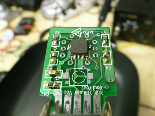
With this said, in response to Reader Number Fourteen’s request this morning for “some code”, I share with you this little thing: Code to Test the Memsic 6202 Accelerometer. You may remember this little guy. We used it in our early foray into fabricating surface-mount electronics. With kitchen skillets. We learned this bit of tinker-y hacker-y from our friends over at Spark Fun. It works great. And it’s cheap as rocks.

I can’t say we were super excited about this particular accelerometer, but that’s okay. It’s just an accelerometer after all. If you follow us down toward the foxhole of these things, you’ll find a whole world of accelerometer fanatics with plenty of material to fuss with — smart accelerometers, accelerometers that let you know when they’re falling, accelerometers that tell you the time as well as whether they’re falling, etc. You’ll find some material buried here in the blog archives, to be exhumed with the right incantation of search and category selection parameters.

This code was written for the Atmel 8-bit microcontrollers that live on the Arduino board. It also makes use of the Wire library for the Arduino, and, as well, the two-wire interface (TWI) hardware support on those microcontrollers, making the whole thing pretty easy-peasy.

#include
#include


// TWI (I2C) sketch to communicate with the Memsic MXC6202J accelerometer
// Using the Wire library (created by Nicholas Zambetti)
// http://wiring.org.co/reference/libraries/Wire/index.html
//
// On the Arduino board, Analog In 4 is SDA, Analog In 5 is SCL
// These correspond to pin 27 (PC4/ADC4/SDA) and pin 28 (PC5/ADC5/SCL) on the Atmega8
// Know You're Microcontroller. Check Which One Is On Your Board/Arduino.
// Newer (as of May '09) Arduinos Use The Atmega168. Can You See It?
// The Wire class handles the TWI transactions, abstracting the nitty-gritty to make
// prototyping easy.

void setup()
{
  Serial.begin(9600);
  Serial.println("Naah??");
  Wire.begin(); // join i2c bus (address optional for master)
}

void loop()
{

  byte x_val_l, x_val_h, y_val_l, y_val_h;
  int x_val, y_val;
// transmit to device with address 0x1D
// according to the MXC6202xMP datasheet, the TWI/I2C address of is fixed
// at the factory depending on what the "x" in the part name is
// Read The Data Sheet section "I2C Bus Data Transfer" for descriptions
// of what the part expects to receive as its address. If you do not understand
// how this works, you are guaranteed to get lost/confusted/frustrated.
// 00010000b is the address of the chip I have, or 0x10

  // a little fuzzy in my recollection here. I think this initializes the chip
  // by setting some bits in the Memsic device's 8-bit internal register
  // Not 100% sure why I initialize two bytes.
  Wire.beginTransmission(0x10);
  Wire.send(0x00);
  Wire.send(0xF0);
  Wire.endTransmission();

  delay(100);

  Wire.beginTransmission(0x10);
  Wire.send(0x00);
  Wire.endTransmission();

  // request five bytes of data
  // first one is the internal register, we can ignore that, but lets look at it for giggles
  Wire.requestFrom(0x10,5);
  while(Wire.available()) {
    Serial.print(Wire.receive(), HEX); // drop the internal register on the floor..
  }
  Serial.println("****");

  // next byte is the MSB of the X axis acceleration
  if(Wire.available()) {
    x_val_h = Wire.receive();
  }
  // next byte is the LSB of the X axis acceleration
  if(Wire.available()) {
    x_val_l = Wire.receive();
  }
  // next byte is the MSB of the Y axis acceleration
  if(Wire.available()) {
    y_val_h = Wire.receive();
  }
  // next byte is the LSB of the Y axis acceleration
  if(Wire.available()) {
    y_val_l = Wire.receive();
  }
  // cobble all of this together into 16 bit acceleration values
  // doing the usual bit-shift polka
  x_val = (x_val_h << 8); x_val |= x_val_l;
  y_val = (y_val_h << 8); y_val |= y_val_l;
  // spit it all out across the serial port so we can see it
  Serial.print(x_val_h, HEX); Serial.print(" "); Serial.print(x_val_l, HEX); Serial.print("n");
  Serial.print(y_val_h, HEX); Serial.print(" "); Serial.print(y_val_l, HEX); Serial.print("n");
  Serial.println("===");

 Wire.endTransmission();

 // loop and do it again.
  delay(200);
}

Continue reading Laboratories, Accelerometers And Kitchen Crockery

Finding The Way – HMC6352 Digital Compass

Friday March 13, 23:53:41

Since I was asked, and asked again, I’ll toss this technotopia solutions nugget to demonstrate that, despite the evidence demonstrated by recent public appearances and weblog postings, we here at the Laboratory are in fact still fully engaged in connecting wires amongst components. Components take a variety of forms, as do the wires. Sometimes bits of silicon strongly encased in hermetically sealed plastic. Other times, cultural components made of different materials. Observations and their conclusions take a variety of paths and sources of inspiration. We enjoy looking at curious people-practices, inspecting them for insights and stories to be told with a variety of resources: objects, images, words.

And so on. More on this point later.

In the meantime, an eager follower has asked for some simple advice that could have been dispatched in an electronic mailing. Instead, The Near Future Laboratory resources room has decided to fold that information into a weblog “posting.”

Wayfinding, of the digital variety has become exceptionally straightforward for those who are okay with writing a dozen or so lines of code for the handy-dandy Arduino and this HMC6352 digital compass which is available as a breakout board off the rack from our friends at Sparkfun.

The compass will give you a perpetual stream of degrees-heading from magnetic north and has interesting adjustments to let you make offset corrections and that sort of thing. It works simply, as all such things should be. It’s a TWI/I2C device, so you get it on the I2C bus, and send commands to its address (42h). Easy-peasy. If you’re doing anything like setting a RAM or EEPROM register, you send the approrpriate command and address. But, for the most part, you’ll just want to tell it to send heading data, right? That’s simple — send the letter ‘A’ (41h) and back comes the heading data. That’s it. Send an ‘A’, get a heading. Send an ‘A’..get a heading. Over and over, or as often as necessary.

Done.

Here’s some Arduino code to get you going!


#include

// http://wiring.org.co/reference/libraries/Wire/index.html
// On the Arduino board, Analog In 4 is SDA, Analog In 5 is SCL
// These correspond to pin 27 (PC4/ADC4/SDA) and pin 28 (PC5/ADC5/SCL) on the Atmega8
//
// These correspond to pin 27 (PC4/SDA/PCINT12/Analog Input 4) and pin 28 (PC5/ADC5/SCL/PCINT13/Analog Input 5) on the Atemga168
// The Wire class handles the TWI transactions, abstracting the nitty-gritty to make
// prototyping easy.

int address = 0x42 >> 1;
 int reading;
void setup()
{
  // this for debugging the data
  Serial.begin(9600);
  // set up
  CLKPR = (1<<clkpce);
  CLKPR = 0;
  // initialize the HMC6352
  Wire.begin(); // join i2c bus (address optional for master)
}

void loop() {

  Wire.beginTransmission(address);
  Wire.send('A');
  Wire.endTransmission();
  //delay(10);
  Wire.requestFrom(address, 2);

   if(2 <= Wire.available())    // if two bytes were received
  {
    reading = Wire.receive();  // receive high byte (overwrites previous reading)
    reading = reading << 8;    // shift high byte to be high 8 bits
    reading += Wire.receive(); // receive low byte as lower 8 bits
    reading /= 10;
    Serial.println(reading);   // print the reading
  }

//  delay(50);
}

Continue reading Finding The Way – HMC6352 Digital Compass

Autonomous Game Controllers

JCB_01012009__142528_4160_DRV001

Continuing on my strange pursuit of designing weird interfaces that disrupt conventional game interaction rituals, I put together a bit more of my “PSX” project. You probably don’t recall, but this is the project where I’ve created a little “dongle” that can fool a PS2 (or Playstation 3, as it turns out..) into thinking that the dongle is actually a Playstation controller. You can also hook up a real Playstation controller to it and it can “read” the controller buttons and joystick and pass that data through, or do whatever you want with it. It appears as an TWI/I2C device to anything that talks to TWI/I2C devices..like my favorite TWI/I2C talking thing — the Arduino.

You can see here that the dongle — the white box with those annoying, huge Playstation connectors on either end, one male, one female — has four wires going into it. Those are for power, ground and the TWI signals, SDA and SCL. The power and ground are necessary because the Arduino (at least this one here) and the dongle run at different voltages. The Arduino is a 5V device, while the dongle is a 3.3V device, so there’s some level shifting going on inside there.

JCB_03012009__195744_4176_DRV001

190808_200037

So, that’s all fine. It works, etc. But then the question that’s actually more intriguing than building the thing..what do you do with it?

Well, I have some ideas, including hooking up a bike to it and attaching a giant human form kick-boxing dummy to play old school fighting games. For some early fun and nonsense, I connected a Wii Nunchuck up to it to control Playstation games with Wii-y gestures and stuff. Which could be cool if I find the right game, or spend a little more time thinking things through rather than just writing and revising microcontroller firmware to make a TWI controllable device, and doing Catia to CAD-up and print plastic enclosures.

But, in the meantime, I decided to do an absolutely crucial bit of game science. Something that I am entirely sure is mulled over constantly, but never properly investigated. The question is best stated thusly: how long would it take the Little Prince to roll up an entire room based on a random path algorithm?

How long indeed. Well, short answer is a long time. I let it go for about 70 minutes, after which he had just 10 things to go in a particularly tricky location that required rolling across a narrow bridge. At this point, I took over..but check out the 8x speed video anyway!

Katamari Autonomy from Julian Bleecker on Vimeo

I wrote a quick little Arduino code for my PSX dongle to have the Little Prince roll forward and then, after a few moments, make a random directional change. (Or stop, take a load off and look around the world.)

This was all done by sending TWI commands to the appropriate registers in my little DIY Playstation 2 controller emulator. All the buttons and the joysticks can be emulated as to their state through a series of write-to registers. If there’s a controller stuck in the other side of the dongle, there are a complement of read-from registers so you can see if any of the buttons are pressed and how much the joysticks are displaced. (I set up an “escape” buttons sequence — pressing both L2 and R2 — to bring control back to the normal joystick so I could navigate menus or take control over, which I had to do after I realized, with four items left, the completion of cleaning the room would probably not happen before the universe ran out of steam.)

Here’s the Arduino code. Pretty straight forward Wire / TWI library stuff.


#include
#include "nunchuck_funcs.h"

#define is_bit_clear(a, n) (0 == (a & (1<<n)))
#define is_bit_set(a, n)  (1 == (a & (1<<n))

#define is_button_pressed(a, button) is_bit_clear(a, button)
#define is_button_released(a, button) is_bit_set(a, button)

#define BTN_SELECT 0
#define BTN_L3 1
#define BTN_R3 2
#define BTN_START 3
#define BTN_UP 4
#define BTN_RIGHT 5
#define BTN_DOWN 6
#define BTN_LEFT 7
#define BTN_L2 8
#define BTN_R2 9
#define BTN_L1 10
#define BTN_R1 11
#define BTN_TRIANGLE 12
#define BTN_CIRCLE 13
#define BTN_X 14
#define BTN_SQUARE 15

// register addresses in the PSX I2C device
#define W_BUTTONS_0 0x00 // (, ^, start, R3, L3, select
#define W_BUTTONS_1 0x01 // (square, x, o, triangle, R1, L1, R2, L2)
#define W_RIGHT_X 0x02
#define W_RIGHT_Y 0x03
#define W_LEFT_X 0x04
#define W_LEFT_Y 0x05

#define R_BUTTONS_0 0x12 // (, ^, start, R3, L3, select)
#define R_BUTTONS_1 0x13 // (square, x, o, triangle, R1, L1, R2, L2)
#define R_RIGHT_X 0x14 // a value from 0x00 - 0xFF
#define R_RIGHT_Y 0x15 // a value from 0x00 - 0xFF
#define R_LEFT_X 0x16
#define R_LEFT_Y 0x17

// I2C address of the PSX dongle
int psx_dongle_addr = 0x72;
int j;
void setup()
{
  Serial.begin(9600);
  randomSeed(analogRead(0));
  Wire.begin(); // join i2c bus (address optional for master)


// this is the control register. setting it to 1 means that
// we have to tell the PSX device what data to send to the
// Playstation2. Setting it to 0 means that it simply passes
// through the data from the controller to the PS2. We can
// read the state of the contorller at any time.

writeToAddress(psx_dongle_addr, 0x24, 1);
}

// we'll use count to figure out when to change direction
int count = 0;
int buttons;

// mode is used to indicate either "pass thru" where we can use the
// actually real human controller to control the PS2, or to generate
// data via the PSX dongle.
// pressing both L2 and R2 simultaneously toggles the mode
int mode = 1;
byte randomNumber;

void loop()
{
  byte val;
  count++;
  //Serial.println(count, DEC);
 // 0x70 shows up as either ID $20 or ID $E0 on Propeller

/*******************************************/
/*
  BTN_SELECT = $0001
  BTN_L3 = $0002
  BTN_R3 = $0004
  BTN_START = $0008
  BTN_UP = $0010
  BTN_RIGHT = $0020
  BTN_DOWN = $0040
  BTN_LEFT = $0080
  BTN_L2 = $0100
  BTN_R2 = $0200
  BTN_L1 = $0400
  BTN_R1 = $0800
  BTN_TRIANGLE = $1000
  BTN_CIRCLE = $2000
  BTN_X = $4000
  BTN_SQUARE = $8000
**/


// 0x00 write to BUTTONS_0, 0x12 read from BUTTONS_0
// 0x01 write to BUTTONS_1, 0x13 read from BUTTONS_1
// 0x02 write to RIGHT_X, 0x14 read from RIGHT_X
// 0x03 write to RIGHT_Y, 0x15 read from RIGHT_Y
// 0x04 write to LEFT_X, 0x16 read from LEFT_X
// 0x05 write to LEFT_Y, 0x17 read from LEFT_Y
//Serial.println(getButtons(), HEX);
//int buttons = getButtons();
//Serial.print(buttons, BIN);
//  passThruButtons();

if(count > 512) {
  count = 0;
}
//Serial.println(mode, HEX);

// get the buttons
buttons = getButtons();

// mode is used to indicate either "pass thru" where we can use the
// actually real human controller to control the PS2, or to generate
// data via the PSX dongle.
// pressing both L2 and R2 simultaneously toggles the mode
  if(mode == 1 &&
     is_button_pressed(buttons, BTN_L2) && is_button_pressed(buttons, BTN_R2)) {
    mode = 0;
    delay(1000);
  } else
  if(mode == 0 &&
     is_button_pressed(buttons, BTN_L2) && is_button_pressed(buttons, BTN_R2)) {
     mode = 1;
     delay(1000);
     }
 if(mode == 1) {
passThruAllAndShow();
 }
 if(mode == 0)
  {

  writeToAddress(psx_dongle_addr, W_LEFT_Y, 0x00);
  writeToAddress(psx_dongle_addr, W_RIGHT_Y, 0x00);
  passThruButtons();

  if(count == 512) {
    count = 0;

    randomNumber = random(1,5);
        Serial.print("FLIP! ");
        Serial.println(randomNumber, HEX);
    switch(randomNumber) {
      case 1: case 2: case 6:
        writeToAddress(psx_dongle_addr, W_LEFT_Y, 0x00);
        writeToAddress(psx_dongle_addr, W_RIGHT_Y, 0xAF);
        delay(500);
        break;
      case 3: case 4: case 5:
        writeToAddress(psx_dongle_addr, W_LEFT_Y, 0xAF);
        writeToAddress(psx_dongle_addr, W_RIGHT_Y, 0x00);
        delay(500);
        break;
          default:
         delay(500);
         break;
    }
  }

  /*
writeToAddress(psx_dongle_addr, W_LEFT_X, (float)map(nunchuck_accelx(), (float)0x48, (float)0xB0,
                (float)0x00, (float)0xFF));
writeToAddress(pssx_dongle_addr, W_LEFT_Y, (float)map(nunchuck_accely(), (float)0x48, (float)0xB0,
                (float)0x00, (float)0xFF));

writeToAddress(psx_dongle_addr, W_RIGHT_Y, (float)map(nunchuck_joyy(), (float)0x1D, (float)0xDF,
                (float)0x00, (float)0xFF));
writeToAddress(psx_dongle_addr, W_RIGHT_X, (float)map(nunchuck_joyx(), (float)0x1D, (float)0xDF,
                (float)0x00, (float)0xFF));
*/
}

delay(10);
}


//
int getButtons()
{
int result = 0x00;

result = readFromAddress(psx_dongle_addr, 0x13, 1);
//  Serial.print(result, HEX); Serial.print(" ");
result <> 8)); // MSB
  Wire.send((int)(addr & 0xFF)); // LSB
  Wire.send(data);
  Wire.endTransmission();
}

byte readFromAddress(int twi_addr, int addr, int bytes_to_read)
{
  byte rdata;
 Wire.beginTransmission(twi_addr);
  Wire.send((int)(addr >> 8)); // MSB
  Wire.send((int)(addr & 0xFF)); // LSB
  Wire.endTransmission();
  Wire.requestFrom(twi_addr,bytes_to_read);
  while (Wire.available()) rdata = Wire.receive();
  return rdata;
}

Continue reading Autonomous Game Controllers