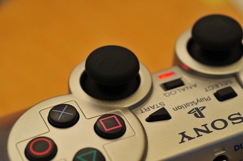

So, this is my analog version of a playful Playstation 2 controller for the PSX project — the one that slows the analog part of the controller down over time so, you know..when I’m playing Katamari Damacy it’s a bit more realistic that the Prince gets tired or during GTA, my guy actually gets tired from running away from liquor store heists and stuff.
I’m looking at two approaches. The first is digital — basically intercepting and modifying the communication between the console and the controller. (I’ve described the protocol, and there’s lots of great, hard-gained information out and about describing how it works.)
It’s a good, playful idea as a kind of theory object, entirely doable, kinda complicated and perhaps a bit of an over-designed solution for a simple idea. What I want is something made (constructed, 3D-printed, wired-up, soldered, fab’d, modeled, fussed-over, troubled-with, a cause of grief, etc.) rather than only just discussed. More than discussing only with words (still the greatest instruments for making things) the object also explicates the tension between physical-digital worlds, or the “real world” and “second life”.
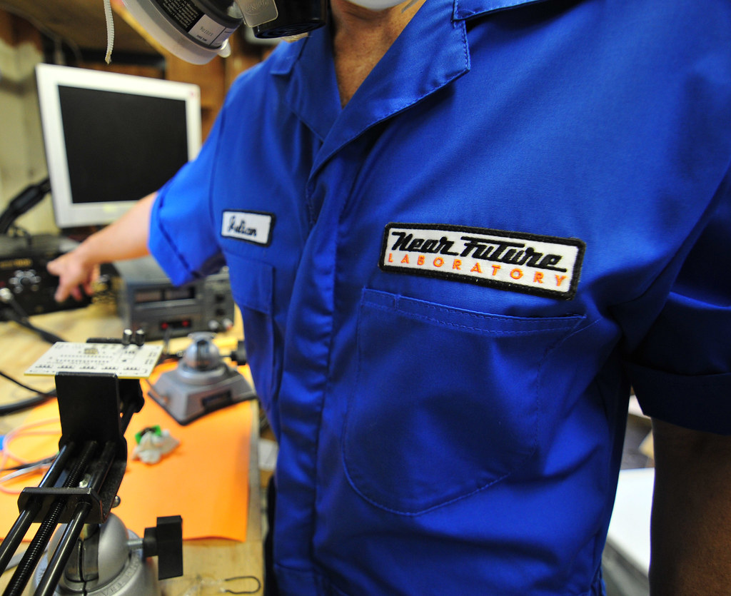
This isn’t something that’s a mass-market product design concept, which should be pretty obvious. (Why is it always assumed that productions from the laboratory are products rather than conversation pieces? I would rather make objects that enter into conversations with a provocation, or enter into discussions, raise questions, help create disruptions by describing new interaction rituals, not making least-common denominator products. These are objects that speak — they create, perpetuate and incite discussions — even inspire new concepts that link 1st life with 2nd life, such as “feeding” characters in games in some fashion, which is closer to the motivation than simply trying to hobble a game character. It’s a theory object. The “theory” embodied in the PSX controller concept here is meant to disrupt the conventional understanding of the relationship between physical activity in 1st Life and virtual-physical-digital activity in 2nd Life digital worlds.)


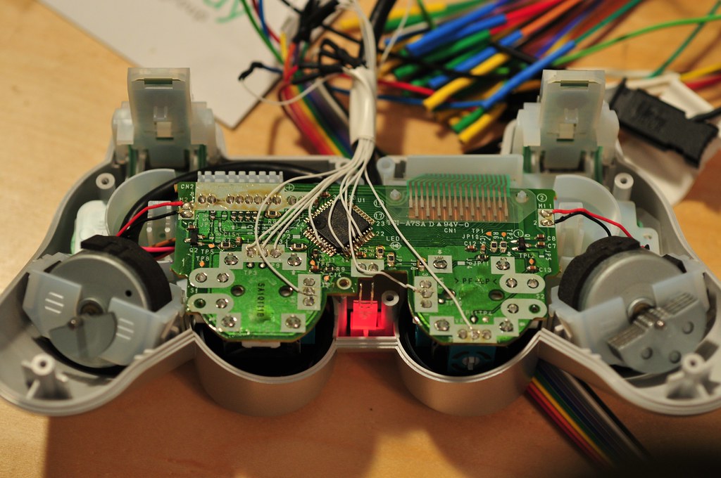
This is the second, more expeditious design. Basically, I tap right into the PSX controller, putting a microcontroller in between the analog control joysticks and the little FPGA or whatever it is that senses the analog control joysticks. So, my microcontroller determines where the control sticks are and, depending on how long the game’s been played, “dampens” the value, constraining its range.
[ad#ad-4]
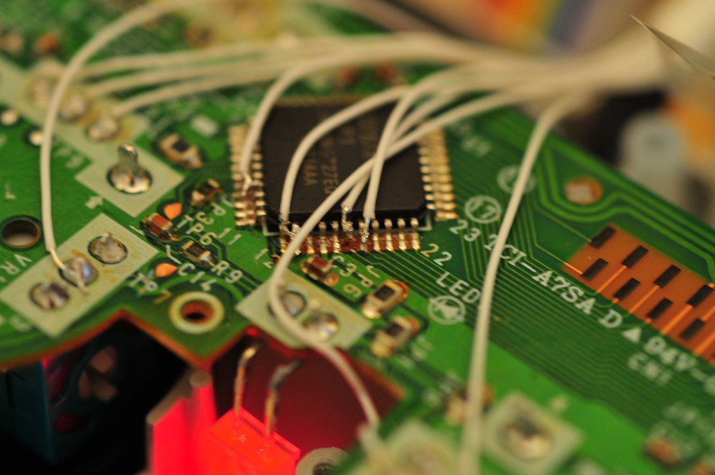
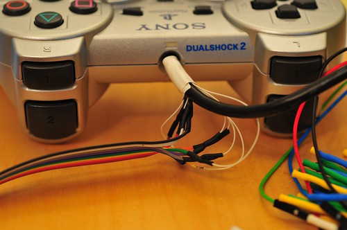
It’s a simple “tap” in between, which requires a bit of less-than-elegant de-soldering and pad lifting (or trace cutting) in order to create the cut-in point for the hardware that’ll sense and then spoof the console.
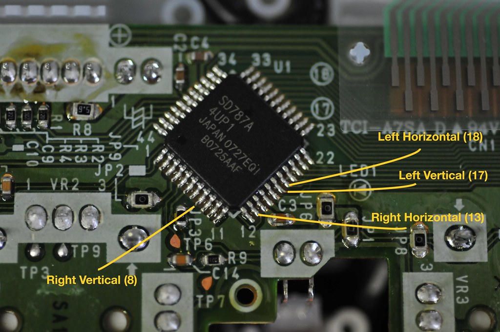
In this case, for testing I used an Arduino, which has enough built-in analog-to-digital converters to sense the positions of the four potentiometers (right-horizontal, right-vertical, left-horizontal, left-vertical) that make up the two joysticks. It also has an I2C/TWI/2-Wire interface that I can use to control four digital potentiometers. The digital potentiometers will appear to be the normal joystick potentiometers only with their values slightly clamped over time to dampen the effects of your normal input.
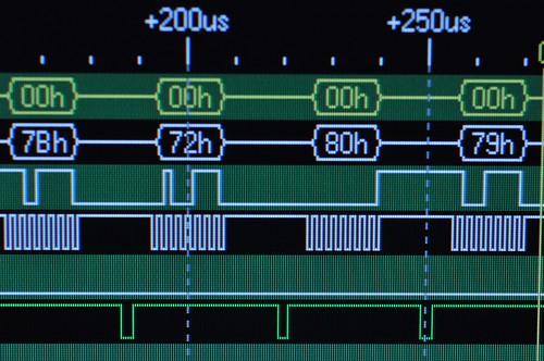
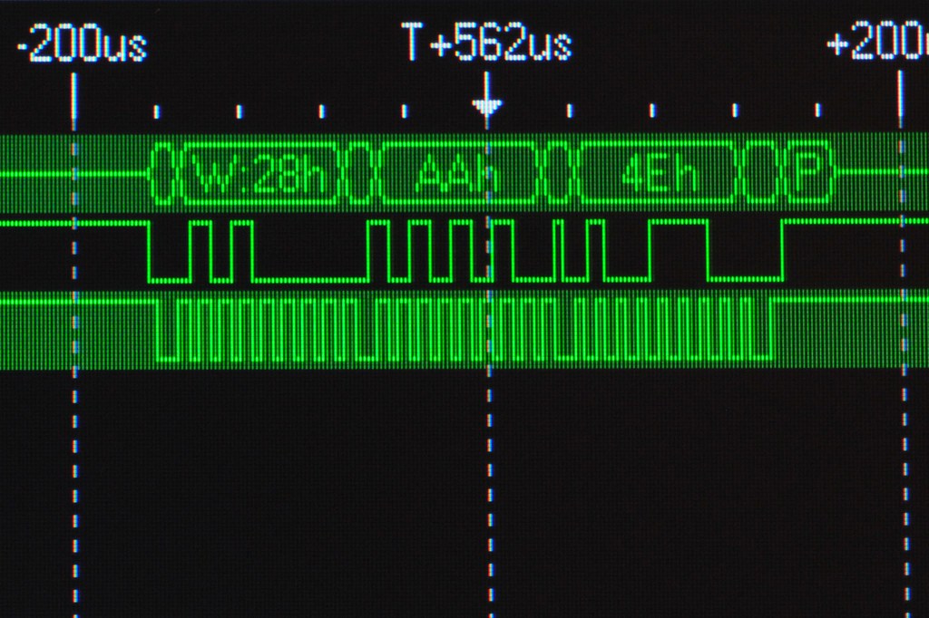
The joystick potentiometers produce 8-bit values in the interface protocol, and are around 0x80 (or so..) in the middle, when they haven’t been displaced. Here’s a snip from the larger interface protocol showing, from left to right and in the white trace, right-horizontal, right-vertical, left-horizontal, left-vertical. Each value is in the middle range meaning that the joysticks aren’t displaced. If, for example, the right vertical joystick was fully displaced upward, the second value would be 0x00 (full down would be 0xFF.)
I wrote a simple little Arduino sketch below that does a 10-bit analog-to-digital conversion of the right and left vertical potentiometers. Because the PSX controller seems to have a limited, 8-bit range, it’s necessary to dampen the 10-bit value. Just through experimenting, I found that dividing the 10-bit A2D value by 6 (sort of like right-shifting 2 1/2 times), I could get pretty close to what the controller was producing in terms of a range of values. (I don’t quite get to 0, but it’s close enough.)
I then test attenuating the range by using a constraint function built into the Arduino extended library. This function “clamps” the range of a value passed into it, so I can (in another version) gradually constrain the range that the potentiometer can go through.
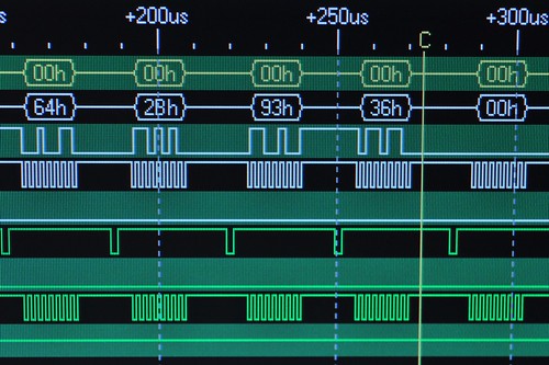
Effectively, for this example, when either joystick is full up, the range of the digital potentiometer is clamped, so that the value that the controller senses is not quite a full displacement, no matter how far the player pushes it up. (The same works for downward displacement.) In this case, full upward displacement clamps the right vertical to 0x2B (second from left) and the left vertical to 0x36 (fourth from left). (You can see that the horizontal displacements are off-center because the joystick has been moved and isn’t dead-center in the horizontal direction.)
//
// Control the Playstation console
// by spoofing the PSX controller

#include
int RY_Pot = 0;
int LY_Pot = 1;

void setup()
{
  Wire.begin();
  analogReference(EXTERNAL);
  Serial.begin(9600);
}

int val = 0;
int bias = 0;

void loop()
{

  // bias runs between about 23 -90 -  155
 // read the value from the right vertical joystick
  val = analogRead(RY_Pot);

 // transmit to device 0x28
 // which is a DS1803 digital potentiometer
  Wire.beginTransmission(0x28);
// prepare to write to potentiometer-1
  Wire.send(0xAA);
  bias = val/6;
 // Serial.print("RX ");
 // Serial.print(val, DEC);
 // Serial.print(" "); Serial.println(bias, DEC);
 // a bit of fudge..
  if(bias < 30) bias -= 10;
  // sends potentiometer-1 value byte
  Wire.send(constrain(bias+15, 60, 120));
  Wire.endTransmission();

 // do the same thing, for the
 // left vertical joystick
  val = analogRead(LY_Pot);

  Wire.beginTransmission(0x29);
  Wire.send(0xA9);
  bias = val/6;
// Serial.print("RY ");
// Serial.print(val, DEC);
// Serial.print(" ");
// Serial.println(bias, DEC);
  if(bias < 30) bias -= 10;
 // sends potentiometer value byte
  Wire.send(constrain(bias+15, 60, 120));
  Wire.endTransmission();     // stop transmitting

  //delay(100);
}