
So — back to hammering and less yammering. I’m trying to build a small, portable, DIY audio mixer. Thus far — I’ve found nothing off-the-shelf that meets my, you know..specifications. There are lots of inexpensive and rather expensive field mixers but those are honking things with gigantic XLR inputs for proper microphones. I want about two 1/8″ stereo inputs, and maybe two or three 1/8″ mono inputs. I want to mix a few things and I want the whole thing about the size of deck of cards or something small like that. The only thing I can think to do is to build it.
Plus..we like to build things.
It should be simple but I’m about a decade out of analog electronics. I used to be able to debug op-amp circuits but not any more. And back when I could they didn’t have the internet the way they have now, so I’m sorta putting it out there with as much evidence of the problem as I can muster.
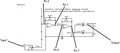
I built the circuit you see above using an LM358 op-amp. Seems like a reasonable go-to unit to build around and many op-amps, as I recall, are generic enough that I feel like it should work in this circuit. (But, I’m prepared to be wrong.)
The problem is that the signal gets super distorted right from the get go.
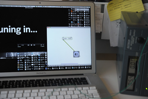
I’m using my MBP to generate a signal using Max/MSP. It’s just a 1kHz pure tone — a sine wave. The output comes out of the computer, right? Max/MSP generates the signal to go out on one channel and that’s what I feed into my circuit.
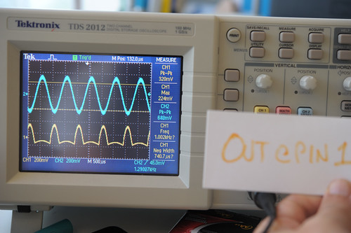
Basically — it gets distorted, even at the input. Check out the signal at pin 2 (the + on the left-most op-amp) — it’s what comes after a resistor and capacitor from the input signal. Why’s it so clipped even before it gets processed except for a couple of discrete components? I think that’s the heart of the issue cause the signal doesn’t even touch the op-amp?
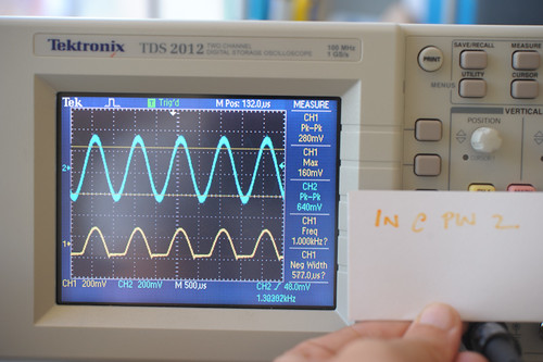
Pin 2 – Basically the input signal after a resistor and capacitor. It’s like..totally clipped there. Why it’s clipped between the raw signal and the input on pin 2 is baffling me. I’ve been so far from analog circuits for so long..I’m just not even sure why putting it on pin 2 alone clips it this way.
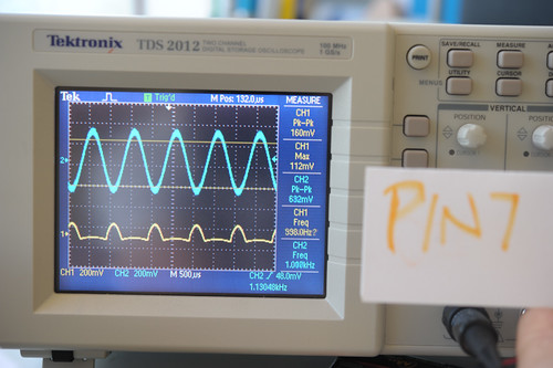
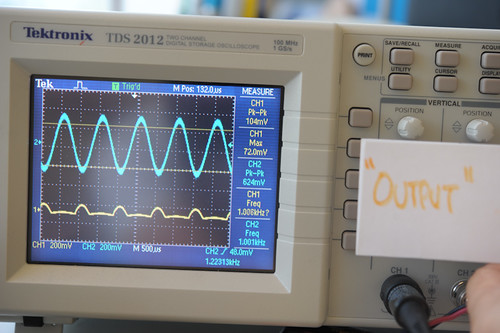
Things only get worse from there. The output of the first op-amp looks like worse crap. This is basically the op-amp processing one signal and mucking it all up.

Why do I blog this? Well..I can’t figure out what might be wrong and because the circuit is so simple, I figure the problem is something as simple as the circuit. But, I may be a bit out of my depth and I’m baffled especially because the signal as measured at pin 2 — effectively the input — is distorted already.
Any ideas?
You feeding a AC signal to a circuit that works in the ground – V+ range. Replace the polarized caps with unpolarized ones, and replace the op-amps with duel supply ones(+-9 volts should work for what you are doing).
If you want to keep your op-amps, you still need to repalce the polarized caps, but a 100k resistor between ground and pin 2, and pin2 and V+. This gives a DC offset to the signal. The output caps remove it again.
One thing not made explicit in your schematic is how you are powering the op-amps. Do you have a split supply or a single supply? (For instance, do you have gnd and +5V or do you have -5V, gnd and +5V rails?) From your scope screenshots it appears to me that you are using a single supply. When you use the function generator to drive the input to your op amp below the supply you are forward biasing a parasitic diode in the device, and a large current is clamping the input to gnd. I suggest putting a 1/2Vcc dc offset on your function generator and reducing the amplitude of the input signal to remain within the supply rails of the op amp at all points and see if there is any improvement.
@LMP @foo You both are right! I hadn’t paid attention to the fact that my audio signal was swinging below my ground! Knot head, I am.. I just glanced at the Pk-Pk and just sort of mentally *shrugged. Thanks! I connected my -V to the negative (-5v) side of my supply and it worked out.
And here, I just attached the V- to the -5V fixed output of my little power supply, and the V+ to the variable output and set it to +5V.
nothing helpful to add but i’ll be keeping an eye on this! i’ve wanted a small portable mixer to combine old mp3 players, minidiscs, etc, anything that makes sound and is portable and is probably obselete- music from a few buttons!
I think I’m close — not that I’m trying to make cold fusion in a mayonaise jar or anything..this should be easy, but then there’s also the fact that I’ve never messed much with sound circuits. I’ve actually been obsessing a bit too much on the potentiometers and their “action” — how well then turn and stuff, which is a bit over the top. I want to combine a mixer that can handle a variety of sources — stereo as well as mono — and line levels and such. At a minimum, it should handle my music player as a stereo source, an additional stereo source and two mono sources. The mono sources should be able to be panned either left or right. I’d like to learn about spatialization of sound in hardware — I think some phase delay might work. For this I’d like it if I could have an “effects send” aspect to this so I can send a source though an “auxiliary processing module” and then have it come back into the mixer…whew..
Consider using log-taper pots if you are concerned. Human hearing is not linear so a linear pot doesn’t ‘feel’ right. Its because the log response of the human ear makes them seem to put too much adjustment range in some areas and not enough in others. Most volume knobs in commercial electronics are log-taper for this reason.
Yep, definitely. I’ve sourced some. I’m also finicky about the “feel” of the potentiometers. The ones I have now have detents..that feels rather digital to me, so I’m looking around for log taper ones that turn with a bit of resistance.