
So — back to hammering and less yammering. I’m trying to build a small, portable, DIY audio mixer. Thus far — I’ve found nothing off-the-shelf that meets my, you know..specifications. There are lots of inexpensive and rather expensive field mixers but those are honking things with gigantic XLR inputs for proper microphones. I want about two 1/8″ stereo inputs, and maybe two or three 1/8″ mono inputs. I want to mix a few things and I want the whole thing about the size of deck of cards or something small like that. The only thing I can think to do is to build it.
Plus..we like to build things.
It should be simple but I’m about a decade out of analog electronics. I used to be able to debug op-amp circuits but not any more. And back when I could they didn’t have the internet the way they have now, so I’m sorta putting it out there with as much evidence of the problem as I can muster.
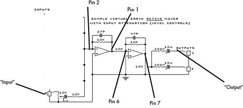
I built the circuit you see above using an LM358 op-amp. Seems like a reasonable go-to unit to build around and many op-amps, as I recall, are generic enough that I feel like it should work in this circuit. (But, I’m prepared to be wrong.)
The problem is that the signal gets super distorted right from the get go.
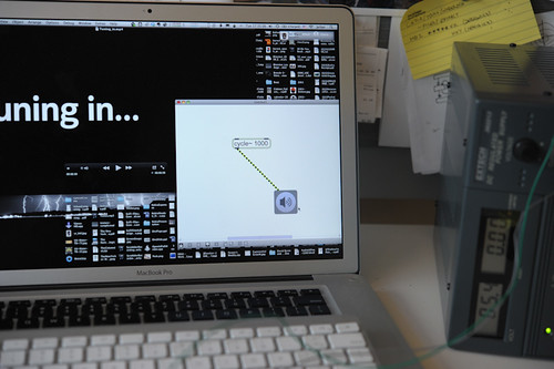
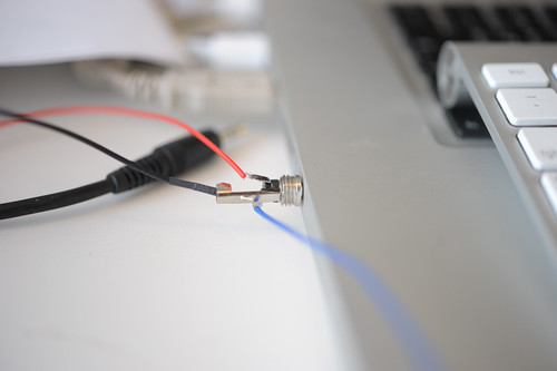
I’m using my MBP to generate a signal using Max/MSP. It’s just a 1kHz pure tone — a sine wave. The output comes out of the computer, right? Max/MSP generates the signal to go out on one channel and that’s what I feed into my circuit.
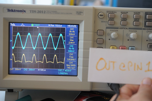
Basically — it gets distorted, even at the input. Check out the signal at pin 2 (the + on the left-most op-amp) — it’s what comes after a resistor and capacitor from the input signal. Why’s it so clipped even before it gets processed except for a couple of discrete components? I think that’s the heart of the issue cause the signal doesn’t even touch the op-amp?
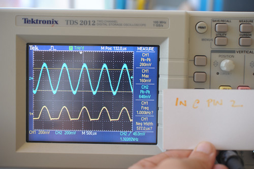
Pin 2 – Basically the input signal after a resistor and capacitor. It’s like..totally clipped there. Why it’s clipped between the raw signal and the input on pin 2 is baffling me. I’ve been so far from analog circuits for so long..I’m just not even sure why putting it on pin 2 alone clips it this way.
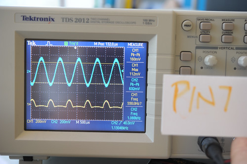
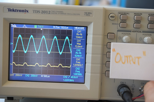
Things only get worse from there. The output of the first op-amp looks like worse crap. This is basically the op-amp processing one signal and mucking it all up.

Why do I blog this? Well..I can’t figure out what might be wrong and because the circuit is so simple, I figure the problem is something as simple as the circuit. But, I may be a bit out of my depth and I’m baffled especially because the signal as measured at pin 2 — effectively the input — is distorted already.
Any ideas?