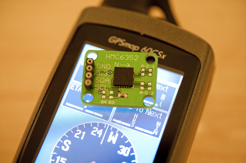
Since I was asked, and asked again, I’ll toss this technotopia solutions nugget to demonstrate that, despite the evidence demonstrated by recent public appearances and weblog postings, we here at the Laboratory are in fact still fully engaged in connecting wires amongst components. Components take a variety of forms, as do the wires. Sometimes bits of silicon strongly encased in hermetically sealed plastic. Other times, cultural components made of different materials. Observations and their conclusions take a variety of paths and sources of inspiration. We enjoy looking at curious people-practices, inspecting them for insights and stories to be told with a variety of resources: objects, images, words.
And so on. More on this point later.
In the meantime, an eager follower has asked for some simple advice that could have been dispatched in an electronic mailing. Instead, The Near Future Laboratory resources room has decided to fold that information into a weblog “posting.”
Wayfinding, of the digital variety has become exceptionally straightforward for those who are okay with writing a dozen or so lines of code for the handy-dandy Arduino and this HMC6352 digital compass which is available as a breakout board off the rack from our friends at Sparkfun.
The compass will give you a perpetual stream of degrees-heading from magnetic north and has interesting adjustments to let you make offset corrections and that sort of thing. It works simply, as all such things should be. It’s a TWI/I2C device, so you get it on the I2C bus, and send commands to its address (42h). Easy-peasy. If you’re doing anything like setting a RAM or EEPROM register, you send the approrpriate command and address. But, for the most part, you’ll just want to tell it to send heading data, right? That’s simple — send the letter ‘A’ (41h) and back comes the heading data. That’s it. Send an ‘A’, get a heading. Send an ‘A’..get a heading. Over and over, or as often as necessary.
Done.
Here’s some Arduino code to get you going!
#include

// http://wiring.org.co/reference/libraries/Wire/index.html
// On the Arduino board, Analog In 4 is SDA, Analog In 5 is SCL
// These correspond to pin 27 (PC4/ADC4/SDA) and pin 28 (PC5/ADC5/SCL) on the Atmega8
//
// These correspond to pin 27 (PC4/SDA/PCINT12/Analog Input 4) and pin 28 (PC5/ADC5/SCL/PCINT13/Analog Input 5) on the Atemga168
// The Wire class handles the TWI transactions, abstracting the nitty-gritty to make
// prototyping easy.

int address = 0x42 >> 1;
 int reading;
void setup()
{
  // this for debugging the data
  Serial.begin(9600);
  // set up
  CLKPR = (1<<clkpce);
  CLKPR = 0;
  // initialize the HMC6352
  Wire.begin(); // join i2c bus (address optional for master)
}

void loop() {

  Wire.beginTransmission(address);
  Wire.send('A');
  Wire.endTransmission();
  //delay(10);
  Wire.requestFrom(address, 2);

   if(2 <= Wire.available())    // if two bytes were received
  {
    reading = Wire.receive();  // receive high byte (overwrites previous reading)
    reading = reading << 8;    // shift high byte to be high 8 bits
    reading += Wire.receive(); // receive low byte as lower 8 bits
    reading /= 10;
    Serial.println(reading);   // print the reading
  }

//  delay(50);
}
