Drowsy LED for The World's Slowest Instant Messenger

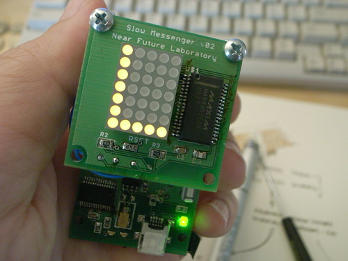
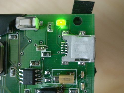
I dunno, I was staring at the Slow Messenger and the power LED — your typical grasshopper green — was so bright and just staring at me and kind of giving me a headache. And I thought..that’s not about slow. And I thought about the drowsy white “sleep” pulse of my PowerBook and I was, like..I need something like that on this device. A slow, sleepy, drowsy pulse. And maybe the pulse will change at different times of the day or something.

Lucky for me I had attached the LED to one of the timer/comparator signals on the ATMega32 in the design.

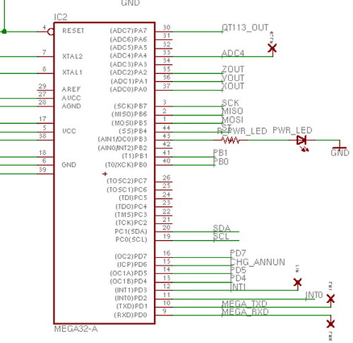
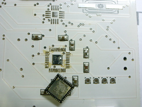
That signal — PB3? Over there on the left side of the Atmega32? That has an “alternate” use as an output for the timer/comparator circuit. That means that it will output a digital signal if you tell it to based on an internal counter equalling (comparing to) a value you specify, or when a timer is done counting up or down. So, by knowing things like how fast the chip is running (8 megahertz in my circuit) you can start to derive how often this signal will get turned on and off. Pretty soon you’re doing pulse-width modulation, something this MCU has built-in facilities for. With PWM you can make an LED think that the voltage being supplied to it is different values. If you change the PWM (and the apparent voltage to the LED) you can get it to dim to varying degrees. Or do a gooey, drozy pulse.

Here’s the code that will do this on an Atmega32. I’m having trouble getting it to work on the Atmega324 (which appears to be a replacement for the Atmega32), but I’ll get that straightened out soon enough..

#include <stdlib.h>
#include <avr/io.h>
#include <avr/interrupt.h>

#include <avr/pgmspace.h>
#include <util/delay.h>

#include "a2d.h"
#include "uart.h"
#include "avrlibdefs.h"
#include "avrlibtypes.h"

/* define CPU frequency in Mhz here if not defined in Makefile */
#ifndef F_CPU
#define F_CPU 8000000UL
#endif

static char mPwrLedLevel = 0;

static void incr_pwr_led(void);

ISR(SIG_OVERFLOW0) {

incr_pwr_led();
}

ISR(TIMER0_COMP_vect) {
incr_pwr_led();

}

static char aDirection;
static void
incr_pwr_led(void)

{
//TIMSK = 0x03;

if(mPwrLedLevel == 0x20) {

aDirection = 1;
}
if(mPwrLedLevel == 0xE0) {

aDirection = 0;
}

if(aDirection == 1) mPwrLedLevel++;

if(aDirection == 0) mPwrLedLevel--;

OCR0 = mPwrLedLevel;
}

int main(void)

{

sbi(DDRB, PB3);
PORTB |= (1<<PORTB3);

for(int j=0; j<30; j++)

_delay_ms(32);
cbi(PORTB, PB3);
for(int j=0; j<30; j++)

_delay_ms(32);
sbi(PORTB, PB3);
for(int j=0; j<30; j++)

_delay_ms(32);

sbi(PORTB, PB3);

for(int j=0; j<50; j++)

_delay_ms(32);

TCCR0 |= (1<<WGM00) | (1<<COM01) | (1<<CS02);

// TCCR0A |= (1<<CS02) | (0<<CS01) | (0<<CS00);
// TCCR0A |= (0<<WGM02) | (1<<WGM00);

// TCCR0A |= (1<<COM0A1) | (0<<COM0A0);

TCNT0 = 0x00;
sbi(TIMSK, TOIE0);

sei();
OCR0 = 0x10;
int j=0x00;

while(1==1) {
_delay_ms(32);
}
}

For the Atmega324 a bunch of registers and bit names in registers changed. This is all documented here:

http://www.atmel.com/dyn/resources/prod_documents/doc8001.pdf

I misread a bunch of it and kind of got a bit fouled up, but finally got it straight. It’s actually pretty simple once you get the registers figured out (things got split up because extra timers appeared and such.)

Basically you want to set up the PWM timer like this:


TCCR0A |= (1<<wgm00) | (1<<com0A1); //PWM Phase Correct, Clear OC0A on compare mach
TCCR0B |= (1<<cs02); // clk/256

TCNT0 = 0x00;
TIMSK0 |= (1<<toie0); // overflow interrupt enabled
OCR0A = 0x10; // start somewhere

Here’s a little CPP class that will run on the Atmega324p and slowly pulse an LED attached appropriately to PB3.


#include <avrlibdefs.h>
#include <avrlibtypes.h>
#include <stdint.h>
#include <stdio.h>

#include <util/delay.h>
#include <avr/io.h>
#include <avr/interrupt.h> // include interrupt support

#include "timer.h"
#ifdef __cplusplus
extern "C"{
//#include "a2d.h"
#include "timer.h"
#include "uart.h" // include uart function library
FILE * uart_str;

} //extern "C"
#endif

static uint8_t mGoLow;

void setup(void);
static void delay_1s(void);
static void delay_600ms(void);
static void delay_300ms(void);

static void incr_pwr_led(void);
static byte mPwrLedLevel = 0x00;

ISR(SIG_OVERFLOW0) {
incr_pwr_led();
}

ISR(TIMER0_COMPA_vect) {
incr_pwr_led();
}

ISR(INT0_vect) {
cli();
sei();
}

static void
delay_600ms(void)
{
uint8_t i;
for (i = 0; i < 60; i++)
_delay_ms(10);
}

static void
delay_300ms(void)
{
uint8_t i;
for (i = 0; i < 30; i++)
_delay_ms(10);
}

static void
delay_1s(void)
{
uint8_t i;
for (i = 0; i < 100; i++)
_delay_ms(10);
}

int main() {
setup();
}

static char aDirection;
static void
incr_pwr_led(void)
{
//TIMSK = 0x03;

if(mPwrLedLevel == 0x10) {
aDirection = 1;
}
if(mPwrLedLevel == 0xD0) {
aDirection = 0;
}
// printf("[[%d]]n", mPwrLedLevel);

if(aDirection == 1) mPwrLedLevel++;
if(aDirection == 0) mPwrLedLevel--;

OCR0A = mPwrLedLevel;
}

void setup()
{
uint16_t *base_addr;
uint16_t k;
float x_sum;
mGoLow = 0x00;
//uint16_t k;

sei();

MCUCR = (1<<ISC01);
MCUCR = (1<<ISC00);
// GICR = (1<<INT0);

sbi(DDRB, 3); // use PB3 as an output

PORTB=0x00;

sbi(PORTB, PB3); // PB3 high, on v04 is pwr led

//TCCR0 = 0x64; // prescaler and other stuff
TCCR0A |= (1<<WGM00) | (1<<COM0A1);//PWM Phase Correct, Clear OC0A on compare match
TCCR0B |= (1<<CS02); // clk/256

TCNT0 = 0x00;
TIMSK0 |= (1<<TOIE0); // overflow interrupt enabled
//sbi(TIMSK0, TOIE0); // overflow interrupt enabled
// TIMSK = 0x02; // overflow interrupt enabled

OCR0A = 0x10;

delay_1s();

cbi(PORTB, PB3);

while(true) {

if(mGoLow == 0x01) {
cbi(PORTB, PB3);
} else {
mGoLow = 0x00;
sbi(PORTB, PB3);
}

}

}

Technorati Tags: ,

MobZombies Sensor Board Assembly

Wow, what a bit of a learning experience this was. That chip is an Invernsense IDG300 gyroscope. $35 a pop. And its one of these “QFN” (quad, flat, no leads) style packages which basically makes it a pain to work with. I thought I could use this technique of dabbing a bit of solder on each of the pads on the printed circuit board and then put a bit of heat to the board with hot air or an iron on each pad. It “took” but there was no electrical continuity. What I think happened is that the big center ground pad took hold, but the other leads didn’t. It seems like it should have. The alignment was good after eyeballing it. Anyway, it didn’t.

So, after taking the thing on and off a few times because of some shorts I found across a capacitor and crap, I decided to have a go with a bit of solder paste. That was something I was trying to stay away from because the paste is messy and difficult to apply to such small leads (.25mm or .01 inch). This is what you really need a stencil for, I guess.

I dabbed a bit, messed it up, dabbed some more, cleaned up, etc. I basically just put paste on the leads that are actually connected to something. There are lots of non-connects, evidently for factory calibration of the device. With the solder paste on, I placed the chip, messed with it for a bit to try to get it aligned good, which is a bit nerve wracking because I’m trying to avoid accidentally spreading the solder paste around and everything. Finally, it looks good and I put some hot-air to the area. It sort of works when I check the electricals, so I try again, finally getting something. One of the devices seems a bit out of kilter — the rates on one axis when its static seems off, but maybe that can be compensated. We’ll see.

Power, but who knows how well it works? The MCUs are fine, power is fine, the Bluetooth radios there are fine. Haven’t had the nerve to check the gyros though..Those things came on and off so many times, I toasted the board a bit.

Technorati Tags:

The World's Slowest Instant Messenger, Part II

Finally, something to show for this “Slow Messenger” project, a playful interface for instant messaging. I’ve gotten all the hardware bits cobbled together and most of the firmware. Now I’m working on learning how to tie in AOL Instant Messenger so that messages can be delivered to the device. Fortunately (I think) AOL has opened their API somewhat. You get some sort of key and then can create your own IM applications based on their protocol and network. I don’t know how well this works, but I suspect if it works well-enough, a preposterous projects like this should be able to make good use of it.

I found one little unexpected design glitch — the LED driver (MAX6953) and the EEPROM I’m using (AT24C1024) have the exact same ‘default’ I2C address (0x50). I stumbled across this while trying to debug why the EEPROM didn’t seem to work, even after an electrical test and crap. You can typically hard-wire the chip to take on one of another possible addresses. On the AT241024 you just wire the A1 pin to either GND or VCC and set the A1 bit of the device address either low or high. The MAX6953 has a similar deal, only a larger matrix of possible different addresses, probably because the chip will typically be found in systems with lots of MAX6953s ganged together to drive large LED displays. In my case, it’ll be easier to make some small hardware changes to the Slow Messenger display board than it’ll be to change the AT241024, which is on a generic Flavonoid board that I want to keep as identical as possible to the other one’s to make managing the firmware easier.

Strange, but I thought that I got closer to having the real-deal I’d understand more about why I’ve committed so much time to doing it. But, I’m no where near understanding why I’m doing it or what it means. This may be beyond the near future and somewhere from another planet.

I heard someone confuse the Near Future Laboratory with corporate R&D. Like, essentially assuming that what I was doing was stuff just around the bend that someone at some corporate lab or product design operation is probably better suited to develop. Whatev. The Near Future Laboratory is the other near future — the one no one in a corporate lab would really think about because the demands of commerce minimize risk, don’t even scratch their heads if the perceived market is too small, and only think about what can be realized to help make next year’s earnings look good. Just to clarify.

Slow Messenger Part III

Technorati Tags: ,

Creative Time: The Book

Many of you know about a collaborative project I worked on a few years back called PDPal. It’s had many iterations and several commissions and just sort of continues to continue, even to this day. Me and my collaborators — Scott Paterson and Marina Zurkow — were commissioned by Creative Time to produce an edition for Times Square, which included a commission to produce a project animation to be shown on the Panasonic Panovision gigantatron screen on the north end of the square, part of the 59th Minute series. Marina created this terribly witty and fun animation. Having it up there over Times Square was pretty fantastic and there are a bunch of pretty fun stories including phone calls in the middle of the night from friends, woozy with drink, calling to say, “heeey..i saaw your thing on the thing..that’s soooo coool.” Around that time I happened to work in Times Square, right there at 1515 Broadway, and seeing PDPal up there every so often always boosted my spirits.

PDPal was an experiment in translating urban mobility and movement into a basis for authoring one’s own story about how cities are experienced. It was a way of making the city resonant and newly interesting by looking at and experiencing it differently. Users were encouraged to document experiences and then “hot-sync” them, so that they would appear on a web-based map of Times Square.

Before Google Maps gave anyone a chance to experiment with what maps in the digital networked world could become, Google gave us the digital equivalent of Rand McNally, which is more than a bit unfortunate. I understand that “maps” are firmly encrusted in our brains as latitude/longitude coordinated instruments, and PDPal enforced this bias towards the literal. People generally had a tough time groking the PDPal Palm Pilot application as mechanism for authoring and situating personal experience. People with PDAs generally are fairly instrumental in their use of such things — calendar and address book, not whimsical art-technology provocations.

If you have a Palm OS PDA, you should be able to download an install any of the three PDPal editions. My favorite is the first one that started it all, commissioned by Eyebeam Atelier.

Eyebeam Edition
Times Square Edition

The Walker Art Center commissioned edition for the Minneapolis Sculpture Garden is not online, but if anyone wants the application file, just ping me.

Anyway, I said all that to say that Creative Time, one of the more successful and, you know..creative public arts non-profits, has come out with a book documenting the projects they’ve commissioned over the years. They’re having a book launch project at Printed Matter in Chelsea NYC on May 5 from 4-7p.