Ambient Self Monitoring

Found this in Tiger, a designer-y inspired bric-a-brac shop in Copenhagen for 10DKK (about $5USD), a prescient little device that allows you to monitor your UV exposure when outside trying to have fun sailboarding and stuff. What I find curious here is the way the packaging simply avoids the unspoken hazard of this cancer mitigation tool — having fun outside is dangerous. Perhaps the Danes, dark-locked for 8 or 9 months a year, are prone to getting carried away with hours and hours of naked sun bathing during the months of nearly ’round-the-clock sun.

I got three of these things, no joke.

Time Spent, Well

I’m generally not a rush-rush guy when it comes to airline travel. If find it useful to take a bit of a time buffer between deplaning and entering the real-world of transfers, taxis, trains, learning to negotiate maps, figuring out where the hotel is, sorting my head out, and to shake off the stiffness of barely human conditions of international travel. So I generally check my bag. I’ve been lucky over the years, only had one rather epic mis-routing of luggage. There comes a time though when the ratio of travel time to luggage retrieval enters the realm of the absurd. Here in CPH, after an hour and change flight from Berlin, a good 30 minutes was spent waiting. Waiting. Waiting. If memory serves, during the last trip they finally just brought the luggage trailing on the flatbed carts you normally only see out on the tarmac. Just drove the tractors in, leaving everyone to climb over things and grab their bag off the cart.

Fortunately the time was well spent having a conversation on the consequences of global connections — what would the world be like if the next billion people were connected? — with my friend Noel Hidalgo (just off his Luck of the Seven round-the-world-for-free-culture trip and a tour of duty trying out being a NYC Cabbie, which might explain the Kangol), who happened to be on the same flight.
Continue reading Time Spent, Well

Comment on Comments

(saschapohflepp)

A pre-emptive and sincere apology to a spate of recent commenter’s comments that were inadvertently relegated to a brimming heap of festering spam. They’re gone, sadly, and there were some that were meant to have replies. Terribly sorry. Terribly un-Web 2.0 of me. Please try again or contact me directly — some of you had questions, and I’m more than happy to help out with what I can and what I know. julian at nearfuturelaboratory dot com.
Continue reading Comment on Comments

When Engineers Design

When Engineers Design

..respectfully. I’m an engineer, too, who is learning Design. But these sorts of things — not done on purpose of course — reveal the seams between purely functional and designed-with-love. This isn’t fun. It works. It gets the job done. But it’s robotron to the point of disrespectfully, especially nowadays. I could understand this if we were in the good old Univac or VAX days. But, ‘cmon.

Anyway. Off to reboot 10 for a day or two of decompiling..

Continue reading When Engineers Design

Companion Species Study Group

Another human peculiar but pervasive human social practice. The introductory manual would be this “Poodles for Dummies” book. I would also recommend these two slightly more advanced instruction books, “When Species Meet” and “The Companion Species Manifesto: Dogs, People, and Significant Otherness” both by my old PhD mentor, Donna Haraway.

Logicport Overview

So, just a brief overview here of the Logicport Logic Analyzer and it’s top-line features and set-up. When I set out to figure this thing out, I took a decent “known” set-up that was running a not terribly complicated, but still useful protocol — SPI. As it happens, the Playstation 2 communication between its controller is roughly the SPI protocol, so that’s as good a test as any, seeing as I had been doing some work with the PS2 anyway.

I wrote a bit about that set up already, so this is the part where I describe how I set the Logicport up. Here are links to two other posts related to the Logicport.

PS2 Logic Analysis
Logic Analyzer

There are three main features of the Logicport I’ll describe — Interpreter’s, Triggers and Measurements. (I’ll also briefly describe some of the basic set-up things that I learned.) Interpreters are like templates for specific protocols. The Logicport supports four protocols as these Interpreter “templates — I2C/TWI, SPI, RS232 and CAN 2.0A/2.0B. For the work done at the Near Future Laboratory, we’re basically covered with these.

Creating a new Interpreter from one of these templates is pretty easy. Just with the case of a SPI Interpreter, your job is to specify which of the Logicport’s channels is probing which of the standard SPI channels. In my setup, I configured two different Interpreters — one for the “master” side and one for the “slave” side. On the master side, the Interpreter probes for the MOSI (master-out, slave-in), SCK (serial clock) and SS (slave select — active low) channels. The “slave” side the Interpreter probes for the same stuff, except the data moves across the MISO (master-in, slave-out) channel.

The Interpreter configuration window also allows you to specify a whole bunch of other useful things. First off is the bit order. The PS2 SPI style protocol sends data least-significant bit first, which is okay, but opposite of the canonical SPI protocol. Fortunately, the Interpreter allows you to specify this. You can also tell it how many bits to interpret as data, and what format you want that data to be represented — Hex, Binary, Decimal, Signed or ASCII. So, that’s super useful.

In the lower image above (click it to enlarge it if you need), I’ve set up this additional slave Interpreter, called PSX-MISO-4, to take advantage of a few additional features of the Interpreter. What I wanted to do was isolate the 5th byte of slave data. So, the fifth chunk of information sent by the slave across the MISO channel. In the PS2-controller communication, this represents the right bank of buttons on the controller — triangle, square, circle, ex — as well as the front triggers — L1, L2, R1, R2. (Here’s more information about the frames of data and what they represent.) So, simply for convenience and to make things easy to interpret, I can specify that this particular Interpreter ignore the first 32 bits of data — four bytes — and just start interpreting and showing the data afterwards. Because I _really_ want to isolate this one byte alone, I also tell it to ignore basically everything else after it does the interpretation of the fifth byte — so I just say, ignore the next 800 bits.

[ad#ad-4]

And, you can see in that second image above, that that one byte is represented in binary, which is useful because each of those switches can be interpreted as a 1 (switch open) or a 0 (switch closed or pressed) without converting from decimal or hexadecimal. Here I’m holding down the triangle and ex buttons simultaneously, so bits one and three are 0.

You can also see that the SPI Interpreter allows you to specify the SPI “mode” — clock phase and clock polarity. This can be useful for trying to figure out how an unknown part is actually operating. In my experience, this can be one of the two or three serious “gotchas” when debugging SPI.

Triggers are probably the first thing you’ll set up, but I guess the second thing I’m describing, partially because I haven’t had any complicated triggering scenarios. In the case of the SPI protocol, you want to trigger when the SS line goes low, or active. This is basically saying that the master is beginning to communicate with the slave, which is usually where your interest starts. And this is what this particular Trigger configuration specifies — Trigger when Edge A occurs once. In the main Logicport window, I specify Edge A as a falling signal on the SS line. Easy-peasy. More complicated triggers could be specified, including the variations you can see greyed out in the configuration window. If you had lots of parallel data from a data bus or something you could specify a specific data value, for example. (One thing that would be nice would be to trigger on a specific SPI MOSI value or a specific I2C device address but for reasons I don’t entirely understand, it was explained to me that this is the equivalent of time travel or something. The work-around is to create a debug trigger on an unused signal from your device to indicate that the thing you want to start watching is now happening and use that signal to trigger the Logicport. Fair enough.)

Finally, Measurements. Another very useful and very configurable-y feature. Measurements use either a set of six movable “cursors”, the trigger point or a specific channel to make time-based measurements. You use this Measurement window to specify what you’d like to measure and what you will use to make that measurement. Here I’m using all of them. First, Measurement A is a frequency measurement, using the built-in Hardware Counter (nice..). With this kind of measurement, I have to specify the source, but not in the Measurement Setup window, strangely enough. In the top of the main window, I specify the Measurement A Source as channel D6, which is the blue/white wire from the Logicport. In this case I have clipped that wire to the clock out (CLKO, PB1) of the Atmega324 that’s sitting on my STK500 break-out board. This simply routes the clock signal that the Atmega324 is using to that specific pin. I’ve got a 16MHz crystal connected to the XTAL pins, and so I see a roughly 16,000,000 Hz frequency measurement for Measurement A, as shown in the bottom part of the main window.

Measurement B is a time interval between Cursor A and Cursor B. That’s basically the clock period of the SCK, the SPI clock, which comes out to be 2uS. Measurement C is the same thing, only the frequency of the SPI clock, or 500KHz. Finally Measurement D is the time between Cursor C and Cursor A, which is the time between SS going low and the first bit of MOSI data, 20.1uS. (I could have also specified “Trigger” instead of Cursor C, which might’ve been more accurate.)

These are the main Logicport features I’ve used to get a basic understanding of how it works. It’s pretty straightforward, particularly for simple set ups like this. The other configurations I’ve had to tweak in order to get good analysis has been the sample rate and the logic levels. I’ve had to vary the sample rate, especially when putting a microcontroller on here that’s faster than the sample rate. With the PS2 on its own, and if I’m not measuring signals from a faster microcontroller, I can slow the sample rate down to 1 or 5 MHz. (Not that it matters a whole lot, unless I want to acquire more total samples.) The logic level specifies what counts as logic high (1) and logic low (0) for the logic analyzer. If you specify it too high, your data will go away, or appear flakey, mostly because the logic analyzer is starting to interpret noise or other spurious signals. And, speaking of noise, the Logicport has four wires that are grey wires with black heat shrink. These are for grounding the device to other things, which is crucial to avoid noise. In the case of my setup, I have one grounding the PS2 and another grounding the STK500 breakout board. This creates a common ground across all three boxes and basically eliminates spurious data and other signaling weirdness.

Security

Security in Peru is all over the place. I don’t know much about the history of things that may cause security concerns — I can imagine — but it’s like driving through a neighborhood with lots of bars on residence windows and security grates in front of retailers. Here, police and militia toting automatic weapons tell their own story.

Playstation 2 Logic Analysis

Back for a bit to the world of prototyping peculiar Near Future kinds of things. I’m still working through this anti-game controller, game controller to do some experiments in alternative sorts of mobile interfaces for traditional game devices.

First, there are two other posts on the Logicport and related stuff, and I’ll just flag them here:

Logicport and I2C
Logicport Overview

I did some quick experiments with the Logicport to get my head around its operating features. (My previous brief analysis is here.) I was mostly motivated to work with a logic analyzer because many of the prototyping sketches I do require some sort of communication between devices using protocols like I2C/TWI, SPI or standard serial communication. If you can get these protocols to work right the first time, then you’re golden. Sometimes though, something goes wrong and debugging can be a pain. I’m the kind of guy who likes to see what’s going on rather than guess, and tools like a digital scope and logic analyzer are indispensable for me. It’s just a preference I have to invest in some pro gear, within a reasonable budget. Seeing as I was trying to get this PSX project done and had trouble debugging it, I figured this was as good a reason as any to go ahead and get it and figure out how to use it.

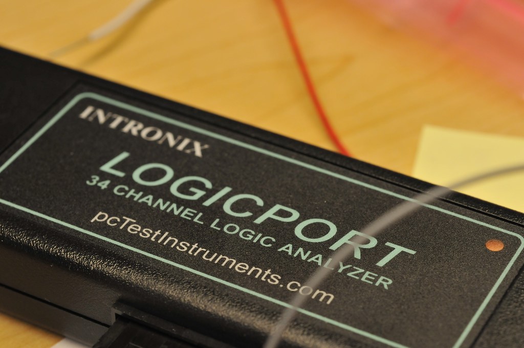
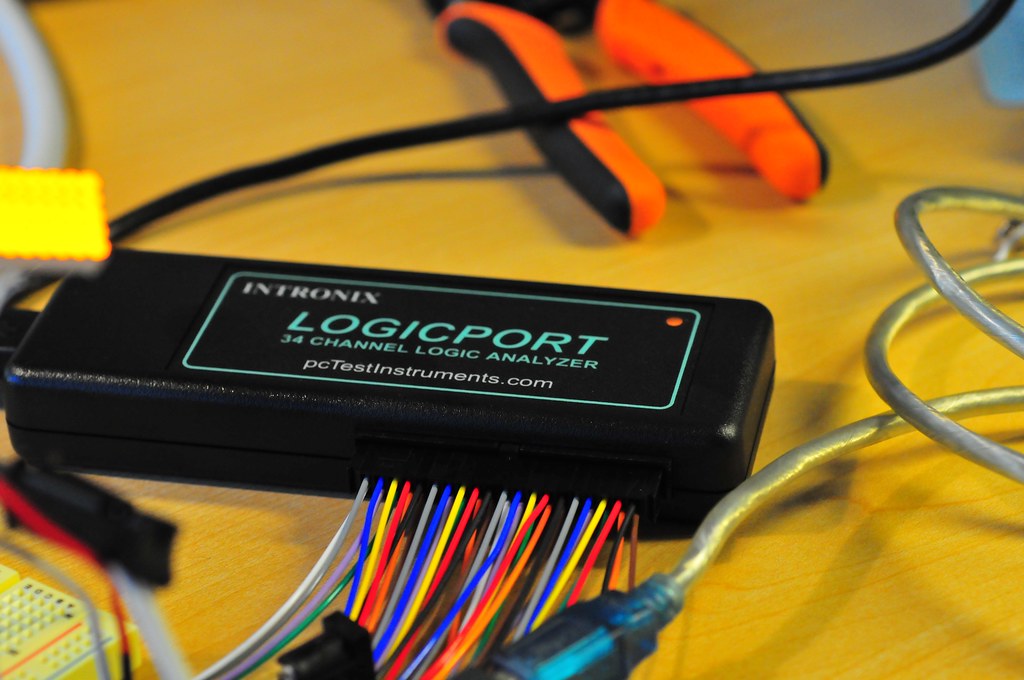
The Logicport is pretty reasonable for a 34 channel (plus 2 dedicated clock channels) logic analyzer because it offloads a lot of the heavy lifting to your PC — $389 with everything you need except the computer. I told myself I’d get one when I had some trouble debugging what should’ve been a fairly straightforward interface — hooking up a microcontroller to a Playstation 2 to make the PS2 think the microcontroller was the normal Playstation controller. This got a bit tricky to debug with just a digital scope that had only two channels with which to analyze essentially a protocol that was using five channels.

[ad#ad-4]

The Playstation 2 interfaces to its controllers using a protocol that is basically SPI (Serial Peripheral Interface). The protocol for SPI is fairly straightforward. There’s a clock (SCK) to synchronize bits of data across two channels: Master Out, Slave In (MOSI); Master In, Slave Out (MISO). MOSI bits are data moving from the master device to a slave device. MISO bits are data moving from the slave out to the master. It’s like a two lane highway of data, with each data bit synchronized by the clock. Additionally, there’s a “slave select” (SS) channel — one per slave device — that tells the slave whether or not it is “active” and should listen to data bits coming across the MOSI channel, or send data bits across the MISO channel. (Reasonably, only one slave device should be active at a time.)

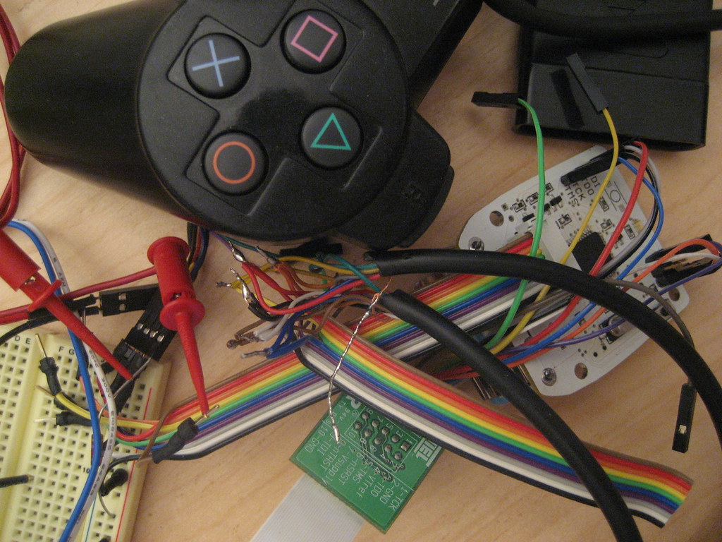
So, that’s four channels. The Playstation 2 actually uses this plus an additional line that is not specifically part of the SPI protocol — an “Acknowledge” (ACK) line. This is used to “acknowledge” to the Playstation 2 console each “frame” of data. That’s just the way it works, and the one feature that is a bit outside of the SPI protocol. (I fabbed-up a simple splice along the Playstation 2 controller cable to watch the protocol and try and figure it out. The splice has a simple IDC-style connector that I can use to plug into to either read the channels or, eventually, connect to a microcontroller.)

There are a few pages online describing the specifics of how a Playstation 2 controller works, including ways to interface the controller itself (the joystick) to microcontrollers.

What I’m trying to do is that, but a bit more, which is to interface a microcontroller that behaves like a Playstation 2 controller to the Playstation 2 console. To do this, the microcontroller needs to respond as a (kinda) SPI slave device, just as the Playstation 2 controller does.

To start this whole business, I tried first writing code “blind” — just looking at descriptions people had put up of how they did this, especially Marcus Post’s work, which has some PIC code to look through. I ported this as best as I could to the Atmel platform (running on a 16MHz Atmega168 on an Arduino), but was having some “hiccups” where quite often the Atmega168 seemed to loosethe protocol. Why? It was hard for me to figure out.

So, two things going on here. One — verify the console-to-controller protocol that the Playstation 2 uses. Two — figure out how to use the Logicport. I’m going to leave two for later, and first show the analyzer crunching on the PS2 console-to-controller communication.

Okay, first thing I did was connect up six of the Logicport’s 34 channels as if we’re analyzing a SPI protocol which, basically, we’re doing. We need MOSI, MISO, SCK (clock), SS (slave select), plus the ACK channel. We also need a ground line to have a common electrical reference. These signals are analogous to the one’s the PS2 uses, only with somewhat different names — they are CMD (MOSI), DATA (MISO), CLOCK (SCK), ATT (SS) and ACK in PS2 speak.

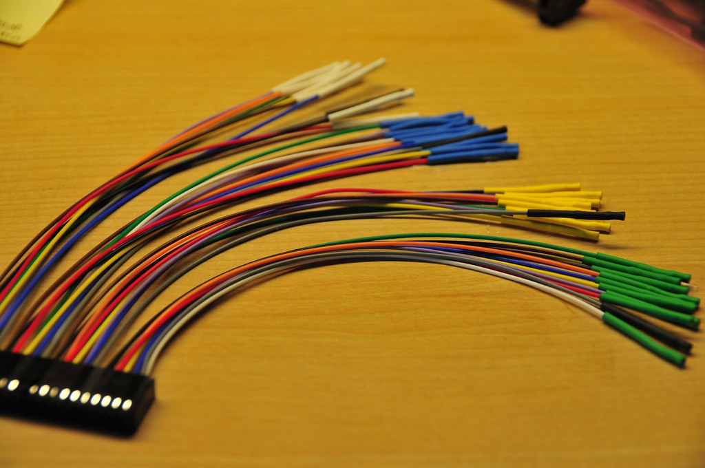
The Logicport breaks up its 34 channels into 4 groups of 9 channels (that’s 36, but two of them are dedicated clock channels), with each group color coded by a bit of heat shrink tubing on the end of a colored wire. This makes it easy to figure out which channel is being represented in the software display. (Here’s a plug module that pops into the Logicport. These are convenient cause you can have one semi-permanently connected to individual projects so you’re not always re-wiring. Just save the Logicport file for each project with the same channels and pop the plug module into the main Logicport box.)

So, I just took the “white” group and connected the MOSI, MISO, SCK, SS and ACK channels from the Playstation 2 “splice” cable. I used yellow for MOSI/CMD, black for SCK/CLOCK, red for SS/ATT, brown for ACK, and green for MISO/DATA. With these signals connected from my “splice” cable to the Logicport, I should be able to start seeing the acquisition. (I’ll go over setting up Triggers and Interpreters in a later post. For now, let’s just see what a little fussing gets us.)

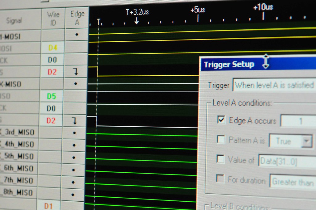
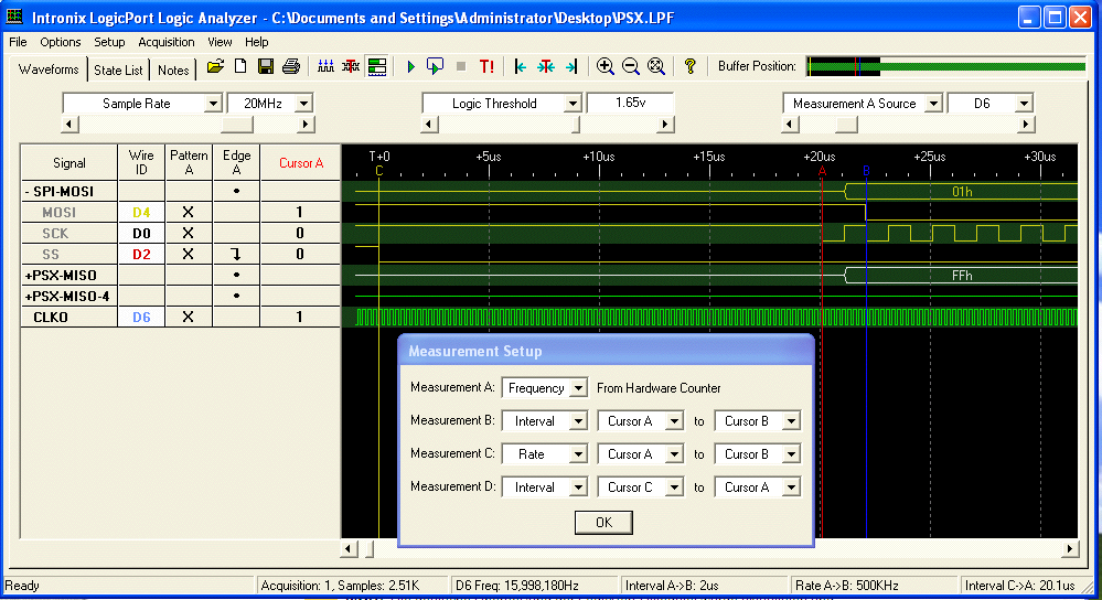
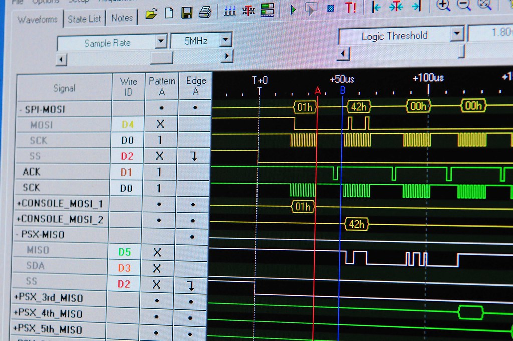
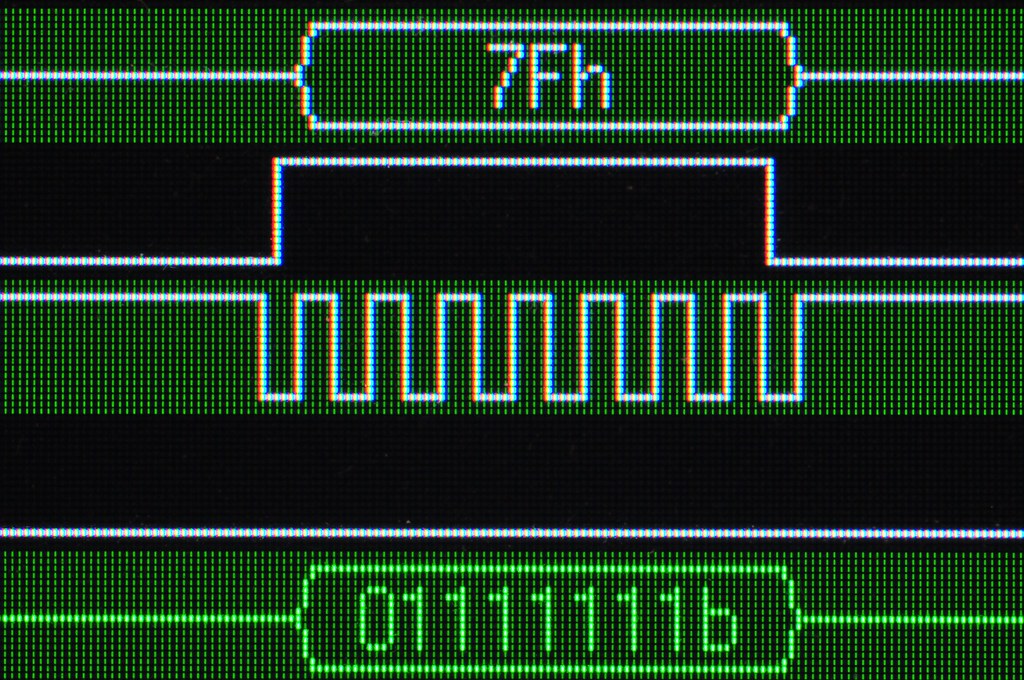
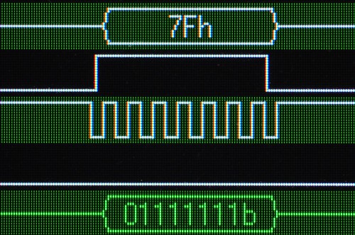
The Playstation 2 protocol is pretty straightforward. It starts out with the console activating the SS/slave-select line (channel D2, red/white) to indicate to the controller to start paying attention. SS is active low, so the channel drops from high to low to indicate “pay attention now.” Following this is a 0x01h byte of data along MOSI/CMD — channel D4, yellow/white. You can also see how the Interpreter can represent the data across a specific channel by aggregating bits and turning them into something useful, like a hex number. (You can also fold up these groups of channels if you don’t want to stare at individual bits.)

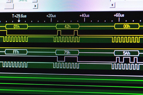
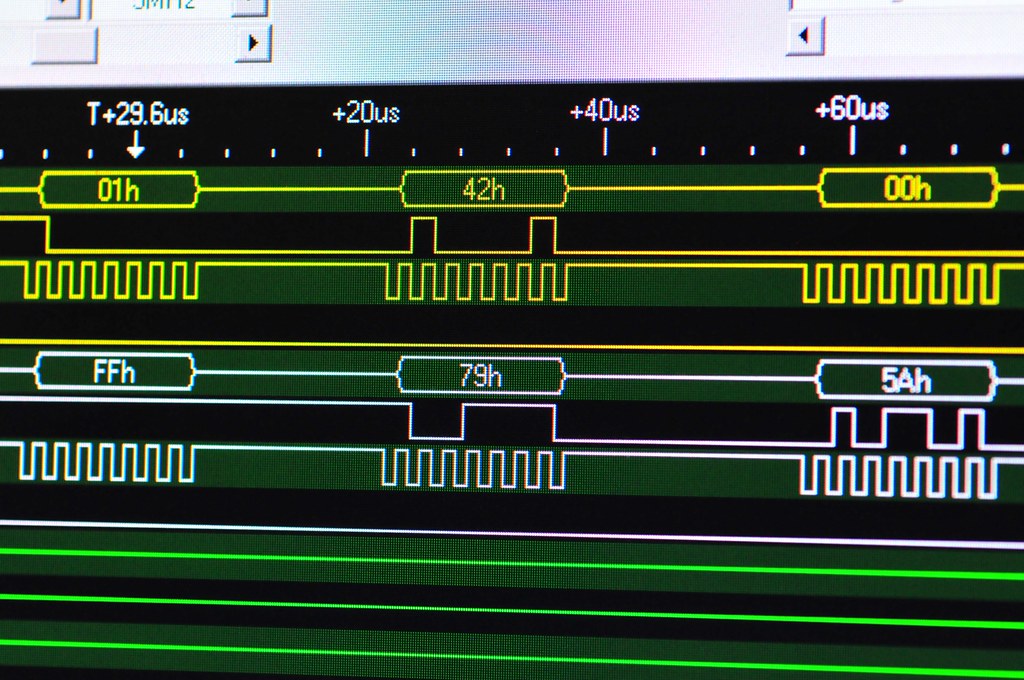
So, this is the basic preamble for communicating between the console and the controller. After the 0x01 the console sends the command 0x42, which basically means — send all your data. Simultaneously, the controller sends back a specific ID to indicate which type of controller it is. In this case, the controller ID is 0x79. Following this the controller sends a 0x5A to sort of say — data is coming.

The data that follows is basically the state of all the controller’s buttons and the analog controls’ positioning. For this controller, there are six subsequent bytes of data. For this particular controller, they’re like this (Here’s a more complete table for other kinds of controllers.):

Analogue Controller in Red Mode
BYTE    CMND    DATA
01     0x01   idle
02     0x42   0x79
03     idle    0x5A    Bit0 Bit1 Bit2 Bit3 Bit4 Bit5 Bit6 Bit7
04     idle    data    SLCT JOYR JOYL STRT UP   RGHT DOWN LEFT
05     idle    data    L2   R2   L1   R1   /   O    X    |_|
06     idle    data    Right Joy 0x00 = Left  0xFF = Right
07     idle    data    Right Joy 0x00 = Up    0xFF = Down
08     idle    data    Left Joy  0x00 = Left  0xFF = Right
09     idle    data    Left Joy  0x00 = Up    0xFF = Down

All Buttons active low.

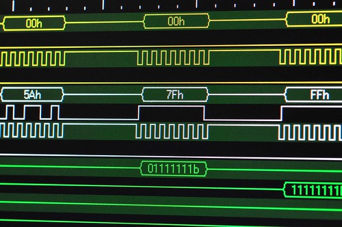
For example, the acquisition image at top shows the “LEFT” arrow button being pushed down on the controller. Huh? Yeah, see — the right most bit in the white trace? It’s actually low — a little hard to tell cause of the angle, but it is. The PS2 spits out data least significant bit first, which means that bit 0 comes before (in time) bit 7, so the 0 at the end is bit 7, and bit 7 in byte 4 indicates whether the LEFT arrow is pressed, and everything is active low here, so a 0 means — pressed. (As I understand it the SPI protocol normally is the other way around, but luckily with the Logicport you can specific the bit ordering.)

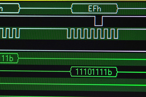
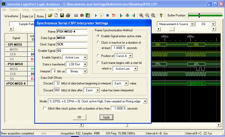
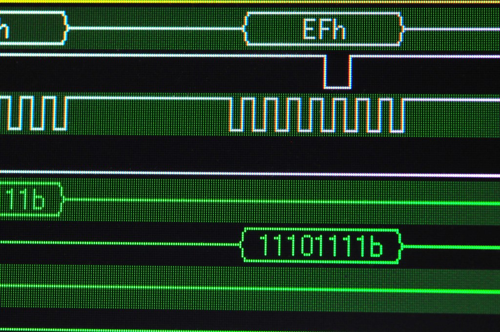
Byte 5 is for the other buttons. This image shows bit 4 activated (low) indicating that the triangle button has been pressed. The bytes that follow are the the joysticks to indicate their positioning along their two (left/right, up/down) axes, running between 0x00 and 0xFF, with their “nominal” (centered) value being about 0x8C-ish, depending on how sticky they are and other things — they’re analog potentiometers which have a little bit of tolerance for variation for mechanical reasons and such.

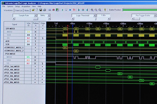
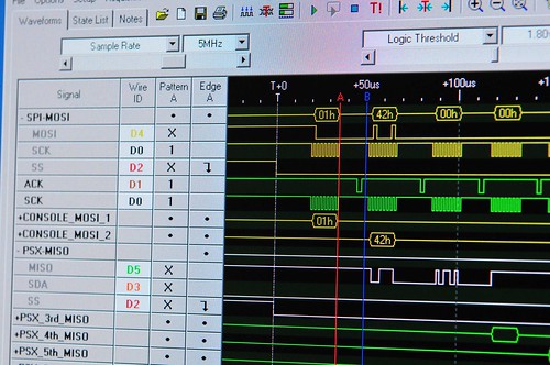
Here’s an overall view of the entire transaction — the three bytes of preamble, followed by six bytes of controller state data starting around the 100uS. (Those bytes are near the bottom, staggered, in green. Next time I’ll explain how I set that view up.)

(Note that the acquisition shows that the console actually holds the SS/ATT signal for the equivalent of another six bytes of data. I’m not 100% sure why, but perhaps there could be additional data bytes for this sort of controller that I’m not getting. In any case, both the console and the controller send nothing back and forth. It’s just clocked nulls for another six bytes. So, off to the right of this image is lots of clock signals, and ACKS, but no meaningful data, until the SS pulls back high. Also notice the ACKS in the fifth channel (green) — these are acknowledge signals sent from the controller back to the console to verify that it’s alive and so forth. Evidently, these are necessary for the communication to work, but not strictly part of the SPI protocol. (Also, I am calling this SPI because it’s close enough, and provides a bit of a context for describing the communication and taking advantage of the Logicport’s SPI Interpreter. Technically I suppose it isn’t SPI.)

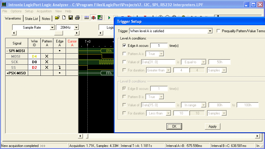
What’s next? Well, a brief overview of how I configured the Logicport to acquire the protocol data. And, now that I can actually see what’s happening and have a better understanding of the SPI-like console-to-controller communication, I should be all set to make a microcontroller behave like a Playstation 2 controller so I can spoof the PS2 and control it from other kinds of things.

[ad#ad-1]