Weekending 12102011

On my side (Nicolas), the week was split between consulting (a workshop about social gaming in France) and different teaching gigs. One of them, at the Swiss Institute of Technology in Lausanne (EPFL), is a year-long course about designer’ approaches and tactics for engineers. We address various methods ranging from user research to prototyping. Given that the course lasts 3 hours per week and that we have not access to any studio facility, we have to do things in a pretty low-fi way. It’s challenging but very intriguing at the same time. This week the course was about mock-ups in interaction design and the role paper could play in this. Inspired by the Post-it phone approach developed by Matt Cottam at CIID, the students had to produce a quick and dirty mock-up of their project. The idea was that they had to rely on the results of the previous courses (field research, brainstorming session).

It was actually the first time I ever tried this approach and it went rather good. Using paper like this was both fun and engaging, especially because I asked students to act out the use of the device; one student being the computer (making audio sounds to mimick the interface), another being the user. This role-play was important as it enabled a “critique” phase afterwards during which anyone of us had to write down the pros and cons of the proposed system and present this to the user and its “computer”. Back to the laboratory, this ideas got me into listing a whole set of workshop activities and tactics that we can deploy on projects.

Over on this side of the world (Julian) most of the work was focused on getting some bits of technology to play together for the Ear Freshener concept for Project Audio. There are some fiddily bits that mostly had to do with not having played with Atmel 8-bit microcontrollers for a long while and their AVR Studio 5 having gone to edition 5 from 4, which meant upgrading it, which meant upgrading the other thing, which meant upgrading that other thing, which meant upgrading that one other thing, which meant upgrading Windows, which meant upgrading the thing that one other thing that didn’t want to upgrade itself, which meant planting my face in both palms and cursing lots of things. I’m also using this new debugger device — the AVR JTAGICE 3 — which as best as I can tell is a smaller thing than the huge AVR JTAGICE that came before it but otherwise the same. That’s finicky, too — but the single wire debugWIRE protocol for debugging is quite nice, although it can get you stuck in debugWIRE unless you know about the one little buried menu item to force the DWEN fuse to reset. That was another thing. I’ll have to do a little action-item post about the process of working with these new tools, for the tool-y people out there.

The result? Thursday night we had a functioning Ear Freshener (or should I say — EarFreshener?) in prototype mode, which you see above. It has a proper continuous adjustment knob that you might think is volume, but you’d be wrong. We went with the microcontroller to control the audio channel selection rather than writing code for the other device, which we’re definitely less familiar with. The extra chip and such won’t make a difference in scale or fitting or anything like that. The goal for this week is to produce some more audio and get Ted or Nick or someone to sit alongside and think about more of the IxD for the thing.

That was good progress by Thursday evening so I gave myself the rest of the week off and went to the Salton Sea for the afternoon.

That’s it.

Continue reading Weekending 12102011

LIS302DL. A 3 Axis Accelerometer

Tuesday July 14, 13.12.21

Ooooh. Those code jockeys in the Laboratory have been mucking about in the ol’ locker room, giving each other rat-tails, chucking firecrackers in the halls and having a good horsin’ around. Smoking cigarettes and drinking cheap booze. Everything. Stink bombs in the girl’s room. Whatever. It’s a regular Lord of the Flies fest on the electronics wing of the Near Future Laboratory. And, look what we found! Some pole dancin’ hardware porn! Step right up! Don’t crowd..

Wednesday July 15, 13.04.33

In reverent honor of my friends and chums who are holding forth with Sketching in Hardware 09 in London and for the solemn sadness I have for not being able to participate this year, I hereby drop some code and hardware science up on this piece of blog with a dozen or so lines of Arduinoness meant to articulate and instrumentalize the wonderful ST Micro LIS302DL 3 axis accelerometer, delivered here via the Sparkfun breakout board. Without further ado, but with plenty of firmware nakedness, here’s the sketch..*slug* this one’s for you, Sketchers..*sob*

#include

// TWI (I2C) sketch to communicate with the LIS302DL accelerometer
// Using the Wire library (created by Nicholas Zambetti)
// http://wiring.org.co/reference/libraries/Wire/index.html
// On the Arduino board, Analog In 4 is SDA, Analog In 5 is SCL
// These correspond to pin 27 (PC4/ADC4/SDA) and pin 28 (PC5/ADC5/SCL) on the Atmega8 and Atmega168
// The Wire class handles the TWI transactions, abstracting the nitty-gritty to make
// prototyping easy.

// We've got two accelerometers connected. You configure the address of each one
// by some wiring
int address_1 = 0x1C; // SDO on the LIS302DL connected to GND makes it at I2C address 0x1C
int address_2 = 0x1D; // SDO/MISO on the LIS302DL connected to VCC makes it at I2C address 0x1D
void setup()
{
  // we'll use the serial port to spit out our data
  Serial.begin(9600);

  byte tmp;

  Wire.begin(); // join i2c bus (address optional for master)


  // Read from the "WHO_AM_I" register of the LIS302DL and see if it is at
  // the expected address.
  // If it is not, spit out a useful message on the serial port. We'll get
  // erroneous data from querying this address, though.
  Wire.beginTransmission(address_1);
  Wire.send(0x0F);
  Wire.endTransmission();
  Wire.requestFrom(address_1,1);
  while(Wire.available()) {
   tmp = Wire.receive();
   if(tmp != 0x3B) {
     Serial.print("Problem! Can't find device at address "); Serial.println(address_1, HEX);
     delay(1000);
   } else {
  // configure the device's CTRL_REG1 register to initialize it
  Wire.beginTransmission(address_1);
  Wire.send(0x20); // CTRL_REG1 (20h)
  Wire.send(B01000111); // Nominal data rate, Device in active mode, +/- 2g scale, self-tests disabled, all axis's enabled
  Wire.endTransmission();
   }
  }


  // Read from the "WHO_AM_I" register of the second LIS302DL and see if it is at
  // the expected address.
  // If it is not, spit out a useful message on the serial port. We'll get
  // erroneous data from querying this address, though.
  Wire.beginTransmission(address_2);
  Wire.send(0x0F);
  Wire.endTransmission();
  Wire.requestFrom(address_2,1);
  while(Wire.available()) {
   tmp = Wire.receive();
   if(tmp != 0x3B) {
     Serial.print("Problem! Can't find device at address "); Serial.println(address_2, HEX);
     delay(1000);
   } else {

  // configure the device's CTRL_REG1 register to initialize it
  Wire.beginTransmission(address_2);
  Wire.send(0x20); // CTRL_REG1 (20h)
  Wire.send(B01000111); // Nominal data rate, Device in active mode, +/- 2g scale, self-tests disabled, all axis's enabled
  Wire.endTransmission();
   }
  }
}

void loop()
{
  Serial.print("1:"); read_acceleration(address_1);
  Serial.print("2:"); read_acceleration(address_2);
}

void read_acceleration(int address) {
  byte z_val_l, z_val_h, x_val_l, x_val_h, y_val_l, y_val_h;
  int z_val, x_val, y_val;
  Wire.beginTransmission(address);
 // Now do a transfer reading one byte from the LIS302DL
 // This data will be the contents of register 0x29, which is OUT_X
  Wire.send(0x29);
  Wire.endTransmission();
 Wire.requestFrom(address, 1);
  while(Wire.available())
 {
   x_val = Wire.receive();
 }
 // This data will be the contents of register 0x2B which is OUT_Y
 Wire.beginTransmission(address);
 Wire.send(0x2B);
 Wire.endTransmission();
 Wire.requestFrom(address, 1);
 while(Wire.available())
 {
    y_val = Wire.receive();
 }

 // This data will be the contents of register 0x2D, which is OUT_Z
 Wire.beginTransmission(address);
 Wire.send(0x2D);
 Wire.endTransmission();
 Wire.requestFrom(address, 1);
 while(Wire.available())
 {
    z_val = Wire.receive();
 }

 // I want values that run from {-X to 0} and {0 to +X}, so a little bit math goes on here...
 if(bit_is_set(x_val, 7)) {
   x_val &= B01111111;
   x_val = -1*x_val + 128;
   x_val *= -1;
 }

if(bit_is_set(y_val, 7)) {
   y_val &= B01111111;
   y_val = 128 - y_val;
   y_val *= -1;
 }

 if(bit_is_set(z_val, 7)) {
   z_val &= B01111111;
   z_val = 128 - z_val;
   z_val *= -1;
 }

 Serial.print(x_val); Serial.print(":");Serial.print(y_val); Serial.print(":"); Serial.println(z_val);
}

Tuesday July 14, 13.09.59

Wednesday July 15, 14.37.44

What’s going on here? Well, straightforward silliness and hardware gafflin’. Two accelerometers on the I2C bus just cause. It looks like this is as many as you can have on there, unless you do some shenanigans or create a second bus with some cleverness.

The hardware spec on the device (Which. You. Should. Read.) explains that, if we’re going to talk to these things using the I2C bus we need to wire CS to the high end of the logic rail, so VCC. This tells the device that we’ll be using I2C protocol. Then we need to address the device. If we connect the MISO (master in, slave out) pin to GND, then the address will be 0x1C. If we connect the MISO pin to VCC, then the address will be 0x1D. So, MISO, in the I2C configuration, controls the least significant bit of the address. This way, without further mucking about, we can have two accelerometers on the bus, which is probably one more than most situations demand, but just in case.

If I were to connect more than two, I would probably go ahead and use the three-wire protocol and have one microcontroller pin per accelerometer dedicated for chip-select (CS). Fortunately, this device supports three-wire protocols, or the SPI protocol.

Tuesday July 14, 13.17.11

The Arduino code example above does some simple preambling — initializing the two devices after making sure they are there. Then it just loops forever, reading accelerometer data from each of the three axes of each one, doing a little simple bitwise arithmetic to make the data from a negative value for negative g (upside down in most situations) to positive g (right side up, in most situations). The initialization stage sets the accelerometer range — that is, the max/min values it will read — to +/- 2g. (The device will support +/- 8g according to the specifications.)

There are some cool additional features that I don’t play with, including some interrupts that can be triggered if the device falls suddenly, or if it is “clicked/tapped” or “double-clicked/double-tapped”, which is kinda cool, I guess. If you can come up with a non-gratuitous scenario. Which is probably harder than it sounds. But, even in your gratuitous-I-double-click-my-glass-of-Porto-to-signal-the-waiter-I-need-more-Porto the device will save you the hassle of trying to do this sort of interaction semantics in firmware and get you back to finishing what you were doing in the first place.

Why do I blog this? Notes on the integration of hardware to firmware to ideas. This time with a “new” accelerometer that has some pretty neat features. After this, we’ll be going to paper-pulp and line drawings for a bit folks.

A New Logic Analyzer and the HMC6352 I2C Compass

25092008_023841

25092008_024008

Two things that’ve been sitting on my bench for a good spell — this HMC6352 magnetic compass with an I2C interface, and the Saleae “Logic” logic analyzer. I figured I could combine the two together, showing how I used the Logic to check out the operation of the HMC6352.

First, the HMC6352 is a pretty easy to use magnetic compass with 0.5 degree accuracy. It’s all wrapped up nicely with a pretty normal I2C interface to a bunch of registers on the device, and command-driven queries for reading the compass heading.

The Saleae “Logic” logic analyzer is pretty sweet for debugging I2C as I’ve mentioned in the past. This one is nice and compact, with a reasonable bunch of logic lines for doing simple analysis. I played with this one for a number of projects over the last few months — mostly I2C projects, which is where most of my interface work is these days. But, the “Logic” will also work with a bunch of stock “analyzers” for RS232 and SPI as well, making it pretty versatile for many situations.

The analyzer is a pretty compact package — 1.6″ square and only .36″ high. So, basically miniature for a logic analyzer. It comes with a 9 conductor umbilical along with E-Z-Hook XKM probes that you can use or not, depending on how you’re hooking up to things.

25092008_024813

25092008_025316

The Logic has a pretty easy-to-use bit of front-end software to handle all the set-up and UI work for the teeny-tiny hardware. It’s a UI that is unlike what you might expect from a bit of Windows-based software. It’s very gooey, using some subtle screen effects and UI elements that, for this OSX guy, are not what I think of when I think of XP. Which is good. It makes using the UI not feel like I’m being forced to drink a Rusty Nail or something for breakfast.

The analyzer samples much quicker than I normally have need for and does so without any problems. I’m usually down in the low range — .2 MHz and 1 M samples is usually plenty for what I’m doing. But, if you need a wider range of samples or a higher sample rate, the analyzer will go all the way up to 24 MHz. Those 9 conductors are 8 data lines plus one ground, so you can analyzer an 8-bit wide bus if you wanted at 24 MHz.

So, I put the Saleae Logic on the HMC6352 circuit to give it a shot. First, the HMC6352 set-up.

Although the HMC6352 has a wide voltage range, I was playing around with a level shifter circuit that was already hooked up to an Arduino on the bench, so I went ahead and just kept that circuit as is. So, the basic set-up is my Arduino I2C lines (SDA and SCL) going through a bi-directional level shifter shifts 3.3V 5V, and then to the HMC6352 SDA and SCL lines. I use yellow wire for SCL and blue wire for SDA.

25092008_024251

25092008_024344

I ended up using the Saleae Logic to dig a bit deeper into the communication between my microcontroller (an Atmega168 sitting on an Arduino) and the HMC6352 as a way to test out the logic analyzer.

First I wanted to just probe the I2C communication. The basic transaction my Arduino code was doing was to send an “A” to the HMC6352. According to the specification sheet, writing an “A” to the device causes it to return two bytes of data — the high-order and low-order bytes of a 16 bit value indicating the compass’ heading. Easy enough. Here’s the Arduino doing just that. First, it sets up the write to the I2C device at address 0x21. Then it writes an “A” which, in the ASCII table, is the value 0x41. (N.B. The spec sheet says the HMC6352 is at address 0x42 but — and don’t ask me why — sometimes the address specified has to be right-shifted one bit in order to “take”. I mean I sort of know why, but I don’t know why this is the case sometimes — a r/w bit thing or something. Too much to bother with, but a good way to make good use of a logic analyzer when you’re stuck wondering why your device doesn’t seem to be listening to you. I learned this the long way and only had a fancy DSO to try and debug it.)

25092008_025019

25092008_025136

25092008_025615

There it is in the top picture. A simple write to the device at address 0x21 with all the ACKs, meaning whatever is out there, heard us and is acknowledging receipt of the write. And, it looks like we get two bytes of data back — a 0x03 and a 0x64. The first byte will be the high-order byte and the second byte is the low-order byte. 0x0364 is 868, which we normalize by dividing by 10, to get 86.8 degrees. Done. I’m pretty sure that’s that. Finally, the measurement features are pretty cool — useful for confirming clock speeds or verifying a bit train. There’s a good use of a simple, pretty inexpensive ($150) logic analyzer that’ll certainly save you $150 worth of your time many times over. Plus, the small size and convenience of USB make it easy enough to fit on your bench and store away or travel around with when it’s not in use. My only quibble is that it’s only for Windows, but that’s a minor one. I don’t really play too hard in the OS religious wars. I run whatever makes my life easier at whatever moment. So, a $200-ish Windows chassis in the laboratory that just runs a few apps like some CAD software and things like my Propeller coding environment, .NET development, software for test equipment like this and AVR Studio 4 — it just helps me get things done rather than being adamantine about which OS religion I’ll adhere to and, then, not getting anything done except spending time porting things from one OS to another or complaining about how much a Windows license costs or whatever.

Wow. Okay. Off my high horse. Check this logic analyzer out. I can recommend it after using it for a few months.

#include

// http://wiring.org.co/reference/libraries/Wire/index.html
// On the Arduino board, Analog In 4 is SDA, Analog In 5 is SCL
// The Wire class handles the TWI transactions, abstracting the nitty-gritty to make
// prototyping easy.
// This sketch has a HMC6352 attached to the I2C bus, through a bi-directional
// level-shifter circuit.
int address = 0x42 >> 1;
 int reading;
void setup()
{

  Serial.begin(9600);

  CLKPR = (1<<clkpce);
  CLKPR = 0;

  // initialize the TWI / I2C Bus
  Wire.begin(); // join i2c bus (address optional for master)

}

void loop() {

  Wire.beginTransmission(address);
  Wire.send('A');
  Wire.endTransmission();
  //delay(10);
  Wire.requestFrom(address, 2);

   if(2 <= Wire.available())    // if two bytes were received
  {
    reading = Wire.receive();  // receive high byte (overwrites previous reading)
    reading = reading << 8;    // shift high byte to be high 8 bits
    reading += Wire.receive(); // receive low byte as lower 8 bits
    reading /= 10;
    Serial.println(reading);   // print the reading
  }

//  delay(50);
}

Continue reading A New Logic Analyzer and the HMC6352 I2C Compass

Timing

Next step, testing the PCB edition of the PSX. I’m back to using a slow, low STK500 to do some debugging. Now that the firmware is fairly well squared away, most of the debugging is either a poorly solder-pasted pin (knock-wood).

I did find a curious little 30 minute bugaboo today. While I was making sure that data was being read properly from a controller by itself, I noticed that bits were being consistently dropped. It looked as though things like button presses on the controller were toggling two bits instead of one, and, for example, the first byte that indicates button presses for things like Start, Select and the direction buttons, was always missing the least-significant bit.

It turns out that the way I am emulating requests and data transfers to the controller is particularly sensitive to timing. I’m not 100% sure what the deal is, but the controller I had been using a few days ago was okay with an 16uS clock period. Now, these two I had lying about the studio weren’t working so great with that period — when I changed the clock to a 40uS period, things clicked back into shape.

(I’m sort of wondering whether the series resistors for the firmware generated clock I’m using is too high — I ended up putting a 1.8k resistor rather than the 1k resistor I have in the breadboard prototype, just cause that’s what I had handy.)

In any case that problem got me to thinking that, as other folks have mentioned, the controllers are sensitive to timing — I may need to add one additional control register to the set up so that this timing value can be adjusted easily, rather than sticking it as a constant in the firmware.
Continue reading Timing

PCA9306 Level Shifter

Persistent nagging problem — shifting logic levels between devices that are fabbed with different technologies so their voltages end up being different. Digital circuits “trigger” based on voltage levels — a logic 1 or high signal is relative to the electrical specifications of the device and the fabrication process of the silicon. (A techie diagram is available here.) It’s not a new problem, but one I seem to be coming across more and more as I use the Arduino to do quick sketches of project ideas, or to stand-in for a more embedded solution that might use another of the Atmel 8-bit devices later on when the design and details are more refined.

I’ve tried a bunch of things, including the kind of canonical reference circuit from Philips that uses the BSN20 MOSFET. Sparkfun has a neat little breakout board using a MOSFET, the BSS138. Same principle, built out for you by the fine folk at Sparkfun.

While poking around some more what cause of this PSX project where I have an Arduino trying to talk to a Parallax Propeller, I found reference to a single-chip solution from TI that’s called a PCA9306, which is that small guy up in the photos above. (Just a hair smaller than an 8-pin SSOP package, which means that it was too small to fit on this SSOP break-out — the pins don’t reach the copper, so I had Igor do some hand work to get that to take hold.
Continue reading PCA9306 Level Shifter

Propeller and Arduino

Not the most exciting thing, but an interesting challenge here. I’m trying to get a Parallax Propeller chip to behave nicely as an TWI/I2C slave with the idea that I’d like to create a pretty much black-box interface that’ll allow a TWI/I2C master to control it for stuff. Ultimately I’d like to use the Propeller in the PSX project. It’ll sit in between a Playstation 2 and a normal Playstation controller, and be available as a TWI/I2C slave, so that another device, that doesn’t really care to figure out how to talk to a Playstation 2 or its controllers can make the PSX box with the Propeller in it emulate, for the Playstation, certain button presses, etc. Or, it could “read” over TWI/I2C from the PSX box and find out what the real controller is doing. Or, it could just read or write from a special TWI register address to make the PSX box (with the Propeller in it) just do a “pass-thru” so that the signals just go straight through as if there were nothing in between.

That’s the theory. In practice, setting up this test jig took more time that I would’ve thought.
Continue reading Propeller and Arduino

Urbanism, Data-Driven


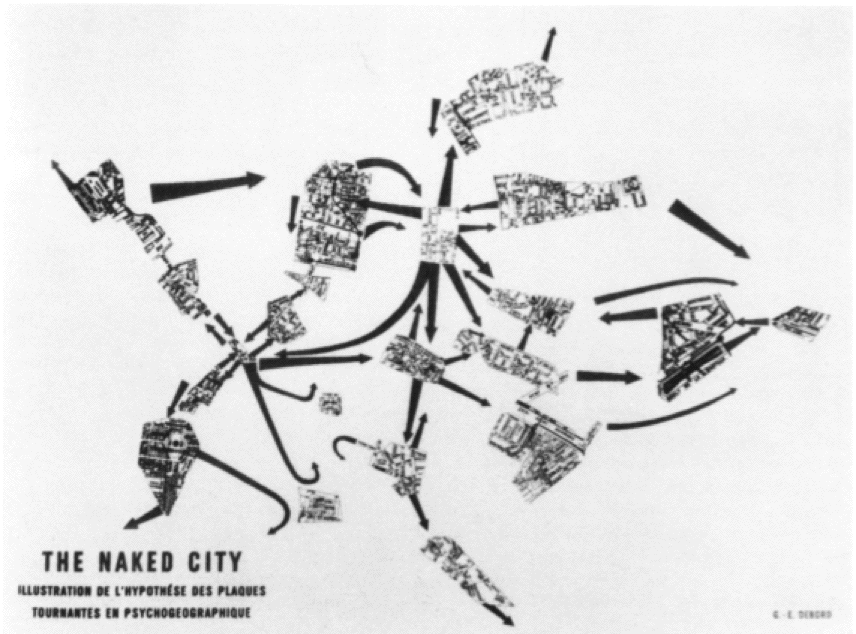
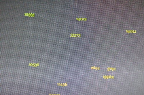
(Some cartogram structures and linkages Pascal created as sensor maps where the geography is an implied and driven — rather than the driving — parameter.)

Fabien Girardin, MIT brainiac and a fellow Near Future Laboratory ‘naut presented his expert and insightful trinity of themes that appear to be the main motivators behind "urban computing", a bit of cocktail party conversation related to this short essay that Kazys Varnelis and Leah Meisterlin wrote, and that Nicolas poked a stick at.

Fabien describes three prime motivators behind the “urban computing” discussion and construction projects. Bears repeating, with some commentary.

1. Creating an opportunistic and optimistic urban environment that is somehow “better” than one without some sort of underlying computational infrastructure. This is the realm of the ubiquitous computing folks. The visions are aspirational — near-future signposts always already just out of reach and endlessly deferred — perhaps this is the definition of industry and academic R&D. Provide curious near-future fictions about possible near-future worlds. Effectively science-fiction expressed through objects and scenarios and large research (instead of film and television production) budgets. (Cf ““Resistance is Futile”: Reading Science Fiction Alongside
Ubiquitous Computing”, Paul Dourish and Genevieve Bell, forthcoming in Personal and Ubiquitous Computing.)

2. Study of the impacts and implications of computational systems and operations in an urban context, performed by GIS folk and urban planners and computer science people. These are studies of the dynamics of data-people sensed in the city, mapped and used to develop insights on urban conditions, or perhaps used as contributing information for design or re-design of urban geography. In some cases the data is interpreted in real-time, such as you might expect to be done to manage loads on cellular data networks, etc.

3. The action, postulating and creative exercises of independent and undisciplinary explorers and adventurers who shuffle and interleave the interesting data points that are anchored to geographies that can be re-mapped. This has brought us such interesting tidbits as the various crime data maps, for example, or the flows of automobiles throughout cities. (Using the geeky, horribly, self-deprecatingly named “mash-ups”.) What is happening here that is most compelling to me at least is that “GIS” activities are becoming something that anyone, without a license or professional sanction can do, inexpensively (i.e. for free and a bit of time). So, anything new here and worth glorifying is this fact — we can be our own map-makers. This is significant in the Foucauldian power-knowledge sense of significant. Cartograms such as the fundraising maps, which started out as a very DIY project, are important because they create new meaning and possibilities for action, or shifts in perspective that can lead to change, rather than stagnation. (There’s a normative element, of course. Visualizations of data with geographies, in the power-knowledge realm of things, are as free to interpretation as anything that alleges to be fact, so they can’t be counted upon to prove much of anything. At worst, they can be enrolled in larger conversations, just like any good knowledge agent.)


(Some more of Pascal’s cartogram structures and linkages. Sensor maps recorded amongst a small group of us and visualized such that the geography is an implied and driven — rather than the driving — parameter.)

I’d add a bit here. How can the experience of space — urban space, just to stick to the most discussed idiom — become fruitfully and playfully data-driven? Mapping data onto geographies by their instrumentalized location in space is okay. It’s a bit knee-jerk, though. What I mean is that re-mapping data with an entirely different basis could possibly produce an entirely different urban experience that may, at worst, be curious and playful. Just to see what comes of this. The Laboratory has been working for way too long on such re-mappings that do not assume that latitude and longitude are the canonical reference points for whatever data gets built on top.

I know..I know. This is weird. And the first project I was involved with that did this — an edition of PDPal that created maps based exclusively on interpreting an “experience” — fought a losing battle. But there are some indicators that this approach is at least worth exploring.

Creating “maps” that have a spatial aspect to them, but that do not use space as the primary or explicit reference datum can then emphasize people-practices or experiences first, with the geographic datum implicit or made into a driven, rather than driving, parameter. Paulos and Goodman’s “Jabberwocky” project comes to mind, as do Twitchr and other mappings of “encounters” and actions that are not expecting to use GPS first-and-foremost.

Situationist Space (Thomas F. McDonough)

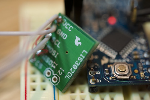
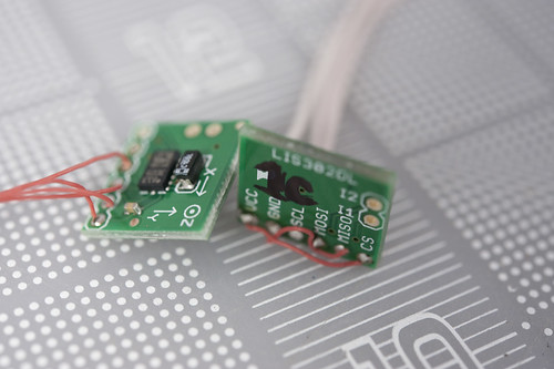
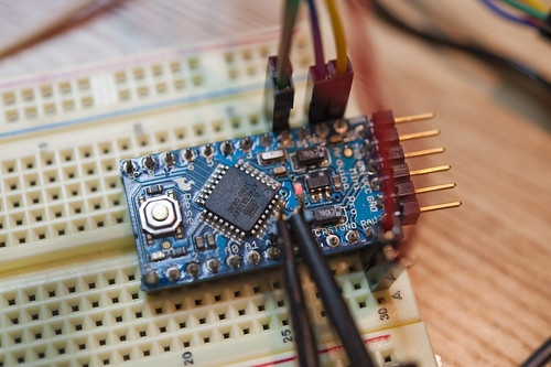
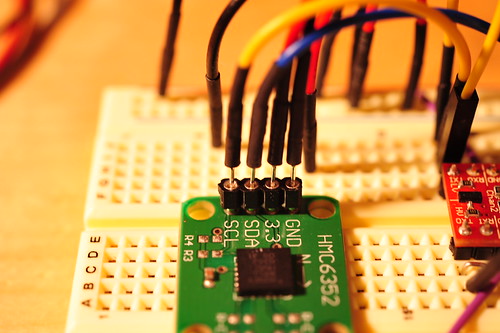
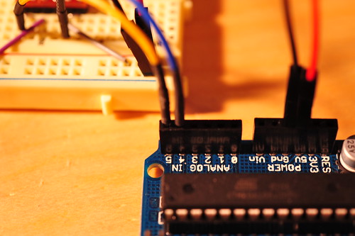
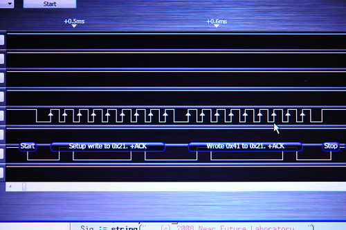
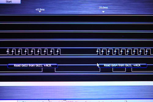
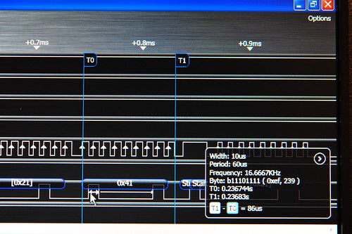
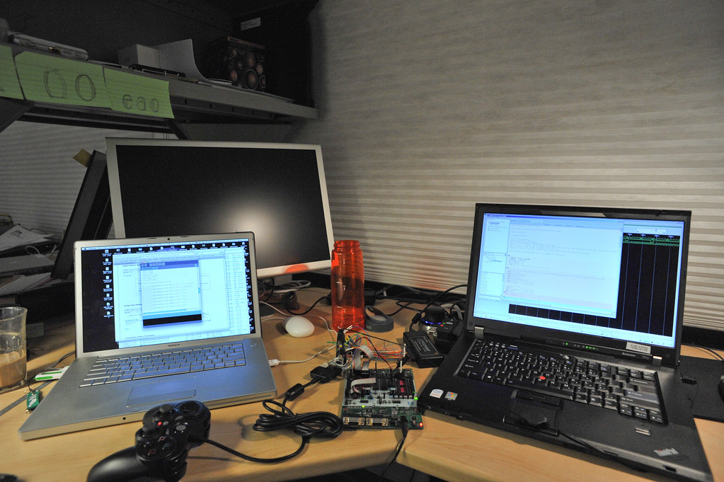
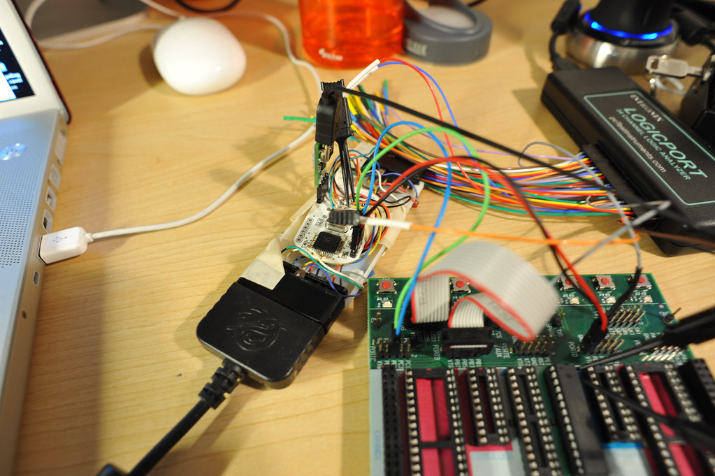
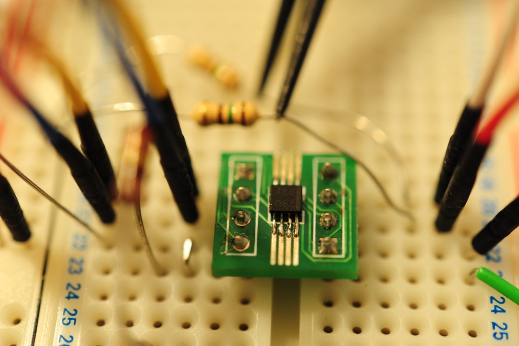
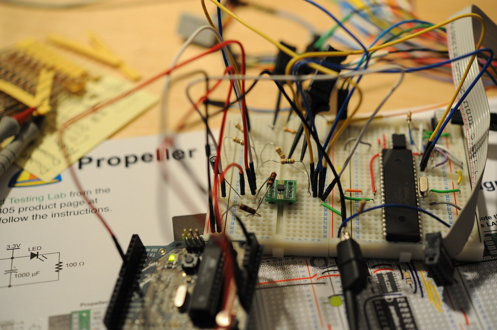
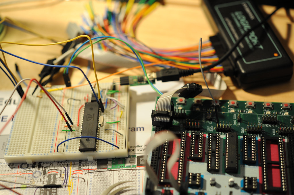
Here in the Laboratory we’ve been building several prototype devices that record Bluetooth encounters for later visualization. The first prototype was a small Python script running on a Nokia N70 phone. It was like a little data attractor that would sniff for Bluetooth devices, and then record them in a log file, and send them to a server to be persisted in a database.

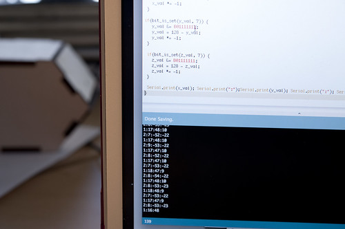
Two recent editions used a small, custom-designed device that used the Bluetooth scanning mode of a radio to essentially do the same thing, storing the results in a Flash memory device to be later extracted with a simple USB interface. Lately a bunch of us in the studio have been working with a similar concept in the form of a background sensing application developed at Nokia R&D for S60 devices that does all of this, plus quite a bit more. (Currently in closed alpha, but soon to be available publicly.) The biggest challenge (besides running it on an S60 device..) is making meaning out of all of this. The strongest vectors for me, at least, lead to re-mapping and exploring possibilities playfully, with no specific expectations that there is intelligence in the maps by themselves.


# install first the following files to your phone
# (they will install automatically the needed libraries for the script below):
# aosocket-series60_v20.sis, pdis.sis
# found at: http://pdis.hiit.fi/pdis/download/pdis/

# this script was found from forum.nokia.com

import e32
import appuifw
##import aosocketnativenew
from pdis.lib.logging import *
##import httplib, urllib
from location import gsm_location
import time
import sysinfo
import select

cell = []
init_logging(FileLogger("e:\apache\htdocs\bt_probing.html"))

def tell(string):
    #logwrite(string)
    if e32.is_ui_thread():
        print string
        e32.ao_yield()

# ----------------------------------
from aosocket.symbian.bt_device_discoverer import *
#from socket import * # for obex file send

def discovered(error, devices, cb_param):
    if error == 0:
        global cell
        #tell("start discovery..")
        cell = gsm_location()

        #tell("devices: " + str(devices))
        tell(cell)
        #print location.gsm_location()
        for address, name in devices:
            logwrite("")

            tell(cell[0])
            tell(cell[1])
            tell(cell[2])
            tell(cell[3])
            print location.gsm_location()
            urllib.urlopen("http://smalltown.nearfuturelaboratory.com/upload_bt.jsp",
                           urllib.urlencode([('addr',address),('name',name),
                                             ('imei', sysinfo.imei()),
                                             ('batt', sysinfo.battery()),
                                             ('signal', sysinfo.signal()),
                                             ('cell_0', cell[0]), ('cell_1', cell[1]),
                                             ('cell_2', cell[2]), ('cell_3', cell[3])]))
    else:
        tell("device discovery failure: error %d" % error)
    _discoverer.close()


# -----------------------------------------------------------------------------


while(1):
    try:
        _discoverer = BtDeviceLister()
        _discoverer.discover_all(discovered, None)
        #tell("discovering")
        e32.ao_sleep(15)
        print "scanning again"
    except:
        tell("init failure")
        appuifw.note(u"Fatal error.", "error")

Continue reading Urbanism, Data-Driven

DS1803 Digital Potentiometer

I’ve been fussing with this digital potentiometer, the DS1803 by Maxim. They’re “digital” because you can control the resistance over its range programmatically, by sending it commands over a 2-Wire (I2C/TWI) serial interface. So, that means that I can hook it up to some microcontroller, like the Arduino, and adjust the resistance in a little program. I chose this one in particular because it can operate at either 3V or 5V, which is convenient, and it comes in a few different models with various resistance ranges. I’m using the DS1803-010, which means it has a range of 0-10K Ohms.

I created a little PCB with two DS1803s on it. Each DS1803 has two potentiometers on it, so I’ve got four on this board. The code for controlling the DS1803 is pretty straightforward. Each one is addressable over the 2-Wire interface, but because we have two on the same interface, I had to configure one to listen to a slightly different address. The details are in the specification sheet, but basically you hardwire the three lines A0, A1, A2 (see the schematic above) to change the address. Effectively you can have up to 8 individually addressable DS1803s on one interface.

In the Arduino source code example below I am only talking with one DS1803 at address 0x28. (if I was talking to to the second one in the schematic, its address was 0x29.) Here I’ve hooked up a logic analyzer to the interface to just make sure we’re communicating. The code below simply adjusts the potentiometer incrementally upward.

[ad#ad-4]

//
// Control the DS1803 Digital Potentiometer

#include <Wire.h>

void setup()
{
  Wire.begin(); // join i2c bus (address optional for master)
}

byte val = 0;

void loop()
{
  Wire.beginTransmission(0x28); // transmit to device 0x28)
  Wire.send(0xAA);            // sends instruction byte,
                               // write to potentiometer-0
  Wire.send(val);             // sends potentiometer value byte
  Wire.endTransmission();     // stop transmitting

  val++;        // increment value
  if(val == 150) // if reached 64th position (max)
  {
    val = 0;    // start over from lowest value
  }
  delay(100);
}


How Hard Hardware

I’ve been pondering a comment Michal Migurski made on Adam Greenfield’s blog about how hard hardware is (he says how easy software is, but in the context of doing hardware)

Even as I plug jumper wires into my breadboard, I’m aware of how much more powerful and easy it is to do things in software, and how much more reach you get through a web browser. Olinda has physical slots for six “friends” on its hardware social unit – revolutionary for a radio, but a meh replacement for an iChat buddy list that *scrolls*.

Why is hardware harder and less powerful than writing some software that can be experienced through, for example, a web browser, or an operating system? Or..is it something about the materiality of hardware that changes things into hard problems to solve. Certainly software is “easier” in the sense that you can more-or-less sit still, get zen and code. And finding the right tools nowadays, with online communities and such makes the route to solving problems less onerous.

I tend to think that it has something to do with the communities — the real toolkits — and their ability, from the grassroots, to work with the material. Both software and hardware have been (and in many instances, continue to be) economic commodities — someone’s trying to make a buck. Nothing wrong with that, of course. But hardware has been particularly expensive, partly because it’s material stuff, with weight and elaborately toxic and costly process costs. But, also because very few companies have had the foresight to consider how free or subsidized hardware could be a smart, strategic investment. Atmel, makers of the microcontroller that goes into Arduino’s, had that kind of foresight. They’ve underwritten most of their development kits so that they literally loose money. Their kits and programming tools are top-notch and it’s barely fair to complain, although some do, and I bristle when a tinkerer grouses about a $30 programming module. This of course from the vantage point of a hardware geek going back to the late 80s, where scoring a Xerox 820 at a Ham Radio fair set me and some buddies back a few hundred bucks, no O/S, barely any documentation. Now you get an open model — everything is revealed to you, there’s support for GCC, etc.
Continue reading How Hard Hardware

Scale

20080526_19-18-15

20080523_11-56-26

Not knowing a heck of a lot about solenoids in practice — I know what they do, and, as an example of the sometimes impracticality of higher-ed, am fairly fluent in the E&M principles at work here. But, when it comes to the practical matter of finding one with the necessary “umph” to articulate a simple controller’s buttons, it’s all guess work.

(Parenthetically, this mechanism is a subcomponent of a larger project called “Air Guitar Hero” which uses a remote glove controller to articulate the solenoids here. Yes. It makes no practical sense. It points to “something” as an experiment, if nothing more than to learn a few things about controlling solenoids and such all. But, mostly it is a design provocation. That’d be the easiest way of describing this whole thing, for those who have asked.)

The first solenoids I used were the smallish ones on top, bought at close-out prices from Electronics Goldmine for about $2 a piece. They couldn’t push the button completely, nor with the surety of purpose the design demanded. They would actuate, but not push the button closed. The best they could do was kind of rattling things around a bit.

Not really knowing precisely how to “engineer” a solution (probably something about determining the closing force of the switch and back-stepping to an appropriate solenoid), I just bought a few different sizes. The first one to arrive was enormous and, had I been a bit more careful, I would’ve realized that the centerline to centerline spacing of a row of four of these would’ve been wider than the center to center distance between the Guitar Hero buttons. Poppa Bear is a Guardian Electric TP12X19-I-24D, push style solenoid, runs at 24 volts. Way too big. So..that one is now a paperweight on my desk.

(Here’s a link to Guardian Electric that has specifications on their other tubular push/pull solenoids.)

The other two were closer, and I ended up using the “Momma Bear” solenoid — a Guardian Electric TP6X12-I-24D, also push style, with a load force of 18-0.06/2.5-0.75 Ounce-Inch. The data sheet is here.

I’m running all of these at 12 volts, which makes them less umph-y, but sufficient for what I’m doing. The solenoids have more push force at the low end of teir travel, so I designed the little supporting bridge there to hold the articulating shaft right on top of the controller button so that most of the force would be committed to pushing the button and not traveling through space.

Speaking of scale, on the left there is the breadboard prototype circuit to drive five solenoids. The right is the PCB with the same circuit (minus a bunch of Arduino icing, just a plain vanilla Atmega168 and crystal). Scaled down, the circuit is much easier to manage and cart around than the relatively fragile breadboard edition, especially cause I’m using janky, untrimmed jumpers to make connections and so forth.

For the curious, here’s the circuit’s schematic and the PCB layout pictures.