High Chair is a tall chair placed on or near the sidewalk allowing sitters a chance to see the city from nearly above. It’s a middle vantage point, above the street, below the skyscraper, with a full view that balconies seldom offer, and still amongst the pedestrian fray. The chair is evocative of that used by a line judge at a tennis match, or a lifeguard’s chair found at the beach. It is approximately 3 meters high as measured from the ground to the seat bottom, light and sturdy to allow it to be easily moved. Integrated into the leg work is a simple ladder for ascent. The chair is wide enough to allow two people to sit comfortably and enjoy the view together.
The chair is meant to be a playful, curious object that disrupts the conventions of the bustling city sidewalk. It allows visitors to spend a moment watching pedestrians from slightly above. It’s a middle vantage point, above the street, below 1st story fire escapes. It’s unlike the view provided by Apple Tours double-decker in that it is still pedestrian, in a way, and engaged in the bustle below.
We plan on pre-fabricating most of the chair and constructing it on-site. While our plans are still preliminary, there are certain considerations that are relevant. Firstly, the chair is expected to be mobile so that it can be shuttled to various locations, or easily moved to avoid hassles with retailers or law enforcement.
(For Conflux 2008 with Pascal Wever, Rhys Newman, Raphael Grignani, Duncan Burns, Julian Bleecker. Drawings: Rhys Newman)
Month: May 2008
Numeric Coincidences

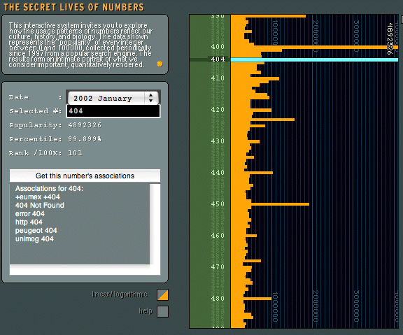

404 resonances. Cars and pages, not found. Not quite plate-of-shrimp; a different category of meaning-making. The above graph is from Golan Levin’s curious “The Secret Lives of Numbers” project, the image below a nicely composed hood shot of a Peugeot 404, the other 404 resonance object, captured by Adam Greenfield in Amsterdam.
Privacy

Privacy, modesty or cocooning?
Ambient Power Consumption Monitoring
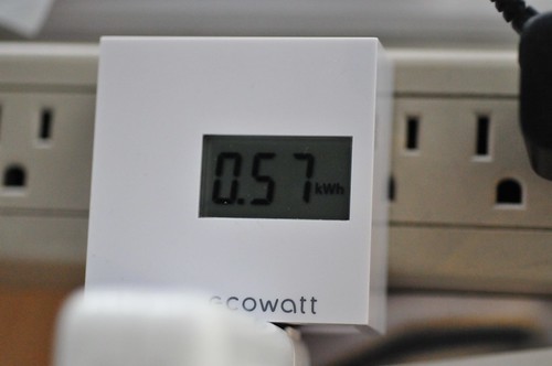
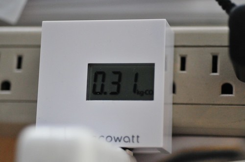
Picked a couple of these “Ecowatt” devices up while in Tokyo, from Bic Camera. They monitor power consumption of whatever you’ve plugged into it. Here I had my MacBook Pro plugged in and running (no sleep) for about 24 hours. The device simply runs through four measurements — two I have no idea about because the symbols are in Kanji, and then two more that are kilowatt hours of consumption and estimated CO2 that would be exhausted from, presumably, a power plant that produced CO2 gas.
There’s lots of work to be done around this sort of idea, first of all a more compelling UI. Maybe even the draconian edition that starts to dim your display or attenuate your Internet as you run past your daily quota of energy.
Continue reading Ambient Power Consumption Monitoring
I2C Logic Analysis
I’ve been doing a bit of business trying to clean up my sometimes wonky skills with I2C communication. It took a bit to figure it out, but I managed to get a few different kinds of devices to the Atmel microcontrollers I usually use — things like a real-time clock, an LIS3LV02DQ accelerometer, these EEPROM devices. Often enough, the first time I connect something new, I confuse some part of the protocol.
Being someone who prefers to see what’s going on rather than poke around and check for what might be a loose connection somewhere, I finally decided to get a logic analyzer. That way, I could take a bit of guesswork out of what was (not) going on. (Sometimes I’ve used my digital oscilloscope, which does the trick too for tracing signals, but then you have to do a bunch of counting bits on the scope — I get confused with such things, especially late at night.)
There are two other posts about this Logicport device, which you may be interested in.
Logicport Overview
PS2 Logic Analysis
(Click the image to try out Cabel Maxfield Sasser’s FancyZoom thingie, pluginifized by Stephen Granade. A new Near Future Laboratory feature!)
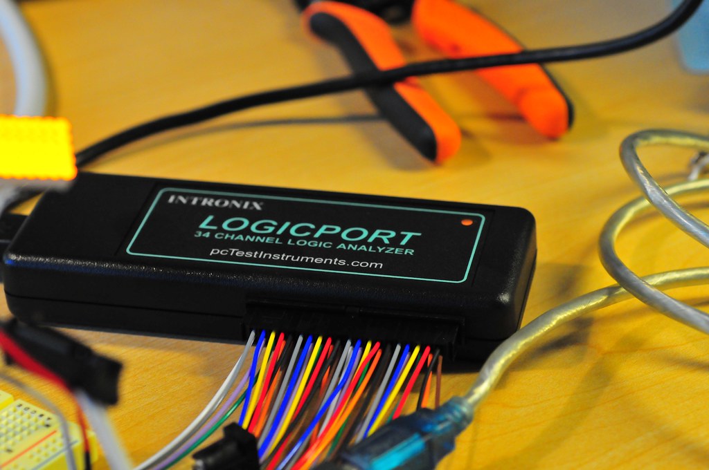
I recently got a hold of one of these Logicport devices from Intronix. It costs $384, and I got a bunch of these nifty “XKM” grabber hook things which are pretty essentially for fastening to small leads or the ends of wires. It’s got 34 channels that it can sample at 500MHz (200MHz if using an external clock..not 100% sure why its slower with an external clock, but okay..), plus built in “interpreters” for some protocols I’m bound to come across, like I2C, SPI, CAN and RS232. The instrument itself connects to your PC (a “PC” PC, not any old personal computer) where the GUI runs. So, unlike a mega-expensive benchtop logic analyzer, you can use a somewhat junker PC and have a decent logic analysis set up for less than $1000. (Or, run Parallels on your Mac and do it there — seems to work just fine.)
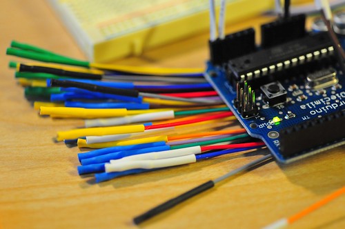
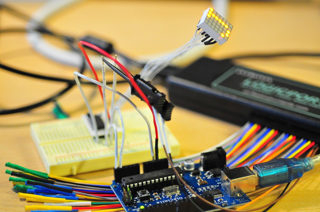
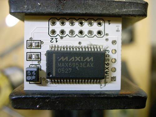
Here’s an Arduino that’s being used to control a MAX6953. The connection to the Arduino and the Logicport is pretty straightforward. Basically, I run an additional wire in parallel to Arduino analog in 4 and 5 which are the I2C lines SDA and SCL respectively. But, you could connect directly to the Atmega168 pins 28 and 27 right there on the chip just as easily if you’re using those useful XKM grabber things.
I mostly got this thing because I end up doing lots of I2C connected device kinda projects, where I’ll have some microcontroller like a PIC or Atmega communicating with some I2C digital potentiometer or display driver, etc. (Ultimately though I was _really_ motivated to get it while trying to get my Playstation 2 to allow itself to be controlled by an Atmega. It should work in theory, but there may be some timing related issues that were proving intractable to debug with just a normal oscilloscope. Hopefully this thing will help.)
I jump in whole-hog..my first Flavonoid prototype had several I2C devices on a single board and I just sort of “hoped” it all would work..This board has three I2C components on it. A DS1307 real-time clock, some EEPROM device there and a MXC6202J accelerometer. (I stopped using the MEMSIC accelerometers, which work perfectly fine, only they’re designed to use these little heaters inside to do their micro-electronic heat convection technique, and that seemed a little squirrely to me. But, that’s just me.)

Here’s basically what you see when you put the Logicport software into I2C interpretation mode. I tell it which of its 34 wires are connected to the two I2C lines (SDA and SCL), start up my development hardware and then click the little start acquisition button.
The I2C protocol is fairly straightforward. Essentially it allows one to use two wires to communicate with up to 127 other devices, each with its own address. The protocol is serial-based, so one of those two wires, called SCL, acts as a clock, while the other one, SDA, serializes data down the wire, one bit at a time. The “other devices” down the wire are slave devices that are under the control of a master, maybe some kind of microcontroller. So long as everything on the wire is well-behaved, they’ll listen for data sent to their unique address and handle commands and data appropriately.
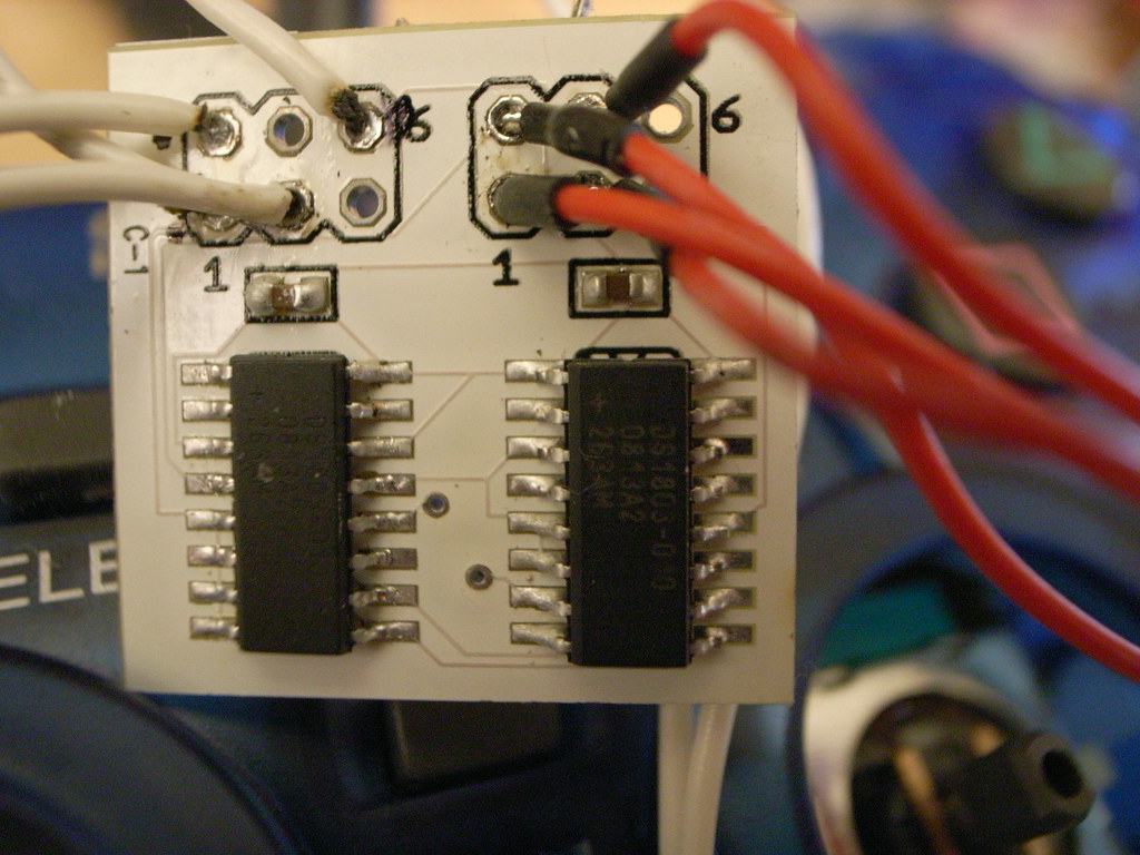
There are safeguards built into the protocol to handle miscommunications, changing over roles between slave and master, multiple masters, etc. The simplest set up — the one I tend to stick with — is one always-and-forever master (a microcontroller, like an Atmega324) and one or several slave devices. There are also contingencies for situations where you want more than one slave of a specific chip. So, for example, here’s a board where I have two DS1803
digital potentiometers. Now, they’re the exact same part number — DS1803 010 (10k digital potentiometer) — and each has factory-burned in the same I2C address. To work around this situation, the part has a three extra pins that you can tie high or low in order to uniquely identify up to 8 of these on one I2C wire.
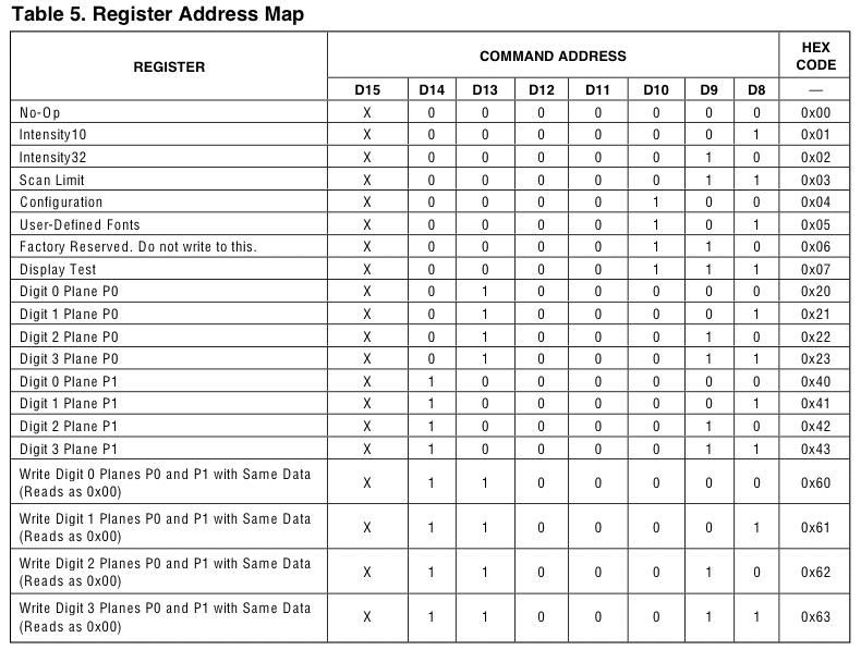
The Logicport and its software begins hunting for the protocol transitions and, hopefully, it’ll find a “start” sequence. In I2C land that’s the master device transitioning SDA from logic high to low while the clock, SCL, remains logic high. So, in that little picture above (click it to blow it up) you can see the mnemonic “S” in the trace indicating the start condition in the top line, where below it the protocol start conditions (SDA high to low, SCL high) are represented. Following that, the I2C protocol expects a sequence of 8 bits representing the slave device address. In this case, I’m testing a MAX6953 which has an address of 0x50h, so all’s good so far. After the end of the slave address is the an “A” which represents the protocol standard “acknowledge” — SDA low while the clock ticks a period. Then there’s this gap followed by another sequence of data which, in this case, is one of several commands I can use to instruct the MAX6953. In this case, the command is represented by a number “0x07h” that is actually an address to a register within the chip.
(It’s a bit confusing, muddling a command code number as a register address — just a bit of memory inside the device — but that can be helpful to think about because many chips using I2C allow you to continue to pump data bytes with the implication that you write the subsequent data to incremental memory addresses, which I describe a bit below.)
According to the MAX6953 specification sheet, allows me to put the display into either “test” mode (all LEDs on) or take it out of “test” mode. By adding an additional parameter to the command, I can control whether it goes into or out of test mode. That parameter is the data that follows the command. In this case, you can see the “acknowledge” and then another sequence of data which happens to be 0x00h — zero. This means that at this point I’m taking the MAX6953 out of test mode and preparing for normal operation. (If I had sent a 0x01h, it would put the MAX6953 into test mode and it would illuminate all of the LEDs in the matrix, useful for testing your wiring and making sure all of the LEDs actually work.)

After all that business — the completion of a command and its parameter, in this case — there’s a final sign-off sequence which is the “stop” in which the clock goes high and then the SDA line goes high and, that’s that. Most of the I2C devices I’ve worked with have some features that allow you to continue sending data before the stop with the following bytes of data going to incremental “addresses.” So, for example, in this case I wrote first to address 0x07, which is a register that lives at address “7” inside the chip. Like this:
If I wanted to write to the next register, I could just send another byte of data, rather than having to start all over again with a new command/address, data, etc. This can save clock cycles, when clock cycles matter. In this case, for a few such writes or reads, it’s not a big deal. In other cases, writing to Flash memory, for example, where you’re writing large blocks of data, it can be really useful and tightens things up nicely.
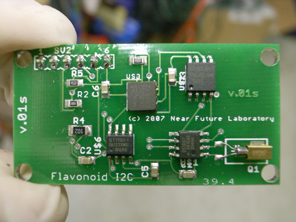
In the PCB below are three I2C components. On the bottom right is a DS1307 I2C Real-Time Clock (you can see the cylindrical crystal used to drive the clock to its right). On the top right is an AT24C1024 1k byte EEPROM chip controlled over I2C. In the kinda top middle is a Memsic I2C two axis accelerometer. By “control” I mean that you can send commands to these to do useful things, depending on what they do. So, for the EEPROM, you can tell it to write data to an address, or read data from an address and send it back across the I2C bus to the master device. The DS1307 can be told to set the day of the month, for example, or say what hour it is.
(A brief design notes about I2C chips. There are lots of them. Often you can find a chip within a family that does the exact same stuff with important variations, like operating voltage differences — 5v versus 3.3v — chip packages — DIP versus surface mount, etc. The useful thing here is that you can swap around as you move from prototyping with an Arduino, for example, which typically wants 5v to run and so the logic rail is 5v for logic high, or a DIP package for easier breadboarding. After all that mess, you can go to smaller, more refined and finished packaging to minimize the footprint.)
(Flickr)
Doing I2C logic analysis with the USB Oscilloscope gives you an image like the one below. It basically shows you the relationship between the clock (SCL) and the serial data line (SDA) and allows you to hunt down gremlins or other problems. How has it saved me? Mostly by saving me time and putting a quick end to real headscratchers.
I have to say, working with I2C has always worked. Eventually. There are two main problems I’ve had.
Number One Problem that I personally have had? Getting the device address wrong, usually by shifting the byte address over in my head by one bit.
Number Two Problem that I personally have had? Forgetting to put pull-up resistors on SDA and SCL. Without pull-ups, the logic levels float too erratically to get a clean and consistent data stream. The logic analyzer will show you stuff, but it won’t make sense and you’ll look at your code and it seems just fine, but the clock and data lines are just floating willy-nilly. So, like..pull-ups. Check that they’re there.

I’ve also tried this USB Oscilloscope thing awhile ago from Hobby Lab. It was relatively cheap — $170 or so, so half as much as the Logicport. (Relative in comparison to the Logicport, and also normal, lab-bench stuff which can run you 100 times as much, easily.) What this sort of device does is offload all the processing and display gymnastics to your PC .
The “box” essentially captures the data, maybe compresses it, and then funnels it across the USB to your PC to figure out how to display it, handling triggering on specific events, etc. The USB Oscilloscope has a digital scope — it comes with a couple of probes like you’d get with a regular scope. But, it also adds a bunch of additional digital channels for sampling up to 16 channels of regular digital data logic analysis, has logic generator feature, so you can pump out sequences of digital data for debugging stuff. I mostly got it for the the logic analysis feature, to help debug I2C and SPI communication when the going go tough.
Here’s a screen shot from a little I2C wrestling using the USB Oscilloscope.
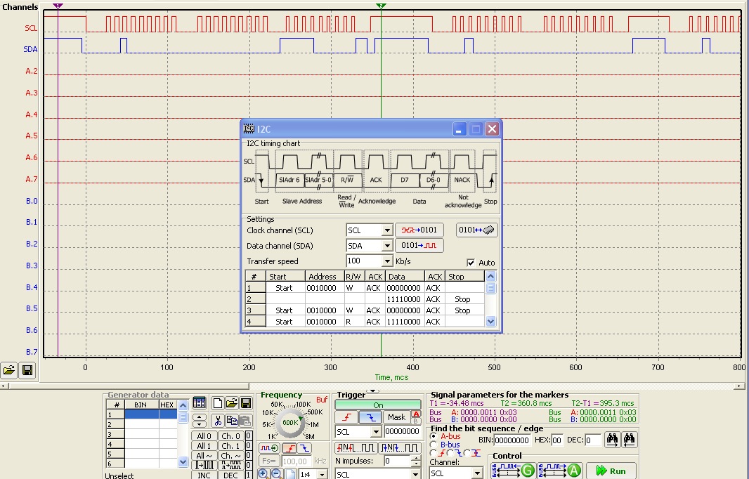
There were a few simple analysis features that I believe shouldn’t be too difficult to integrate into the software, but it may turn out that they are not so easy. For example, I want to be able to trigger on certain I2C addresses for example, but I guess that’d be like looking in the future. (It seems to me that you could just buffer a bunch, look for the I2C address following an I2C start and then trigger on this condition. But, I’m not the expert.) There are work-arounds to such things, such as having the Logicport trigger from another unused output pin on the device, and toggling that pin right before the “sequence of interest.” I also find it peculiar that the analysis can continue over and over again — there must be some way of stopping it after a certain number of I2C “frames” have been captured. Must be.
Additional Resources:
Stuff here at the Near Future Laboratory on I2C
Code to control a MAX6953 from an Arduino, changes the LED matrix to show a number from 0-9 depending on the relative value of a potentiometer connected to Analog In Pin 2 on the Arduino.
#include <Wire.h>
// Using the Wire library (created by Nicholas Zambetti)
// http://wiring.org.co/reference/libraries/Wire/index.html
// On the Arduino board, Analog In 4 is SDA, Analog In 5 is SCL
// These correspond to pin 27 (PC4/ADC4/SDA) and pin 28 (PC5/ADC5/SCL)
on the Atmega8
// The Wire class handles the TWI transactions, abstracting the
nitty–gritty to make
// prototyping easy.
byte i;
int potPin = 2;
int val = 0;
int ledPin = 13;
void setup()
{
Serial.begin(9600);
Wire.begin(); // join i2c bus (address optional for master)
Wire.beginTransmission(0x50);
Wire.send(0x07); // Display Test
Wire.send(0x00); // Normal Operation
Wire.endTransmission();
Wire.beginTransmission(0x50);
Wire.send(0x01); // Intensity16
Wire.send(0x0F); // Full
Wire.endTransmission();
Wire.beginTransmission(0x50);
Wire.send(0x04); // configuration register
Wire.send(0x01); // disable shutdown mode
Wire.endTransmission();
}
void setCharacter(char c)
{
// if(c >= 0x20 && c <= 0x7F) {
Wire.beginTransmission(0x50);
Wire.send(0x20); // Digit 0 Plane 0
Wire.send(c); // N
Wire.endTransmission();
// }
}
void loop()
{
val = analogRead(potPin);
setCharacter(val/100+‘0’);
delay(300);
}
syntax highlighted by Code2HTML, v. 0.9.1
Secure Your Goods
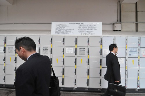
From my paranoia-fueled American mind, this is a curious context for small public storage lockers, immediately outside of the bustling entrance to the Shibuya train station in Tokyo. Whenever my cultural relativity hits a speed bump like this, I know I’m elsewhere. Continue reading Secure Your Goods
Display Driver
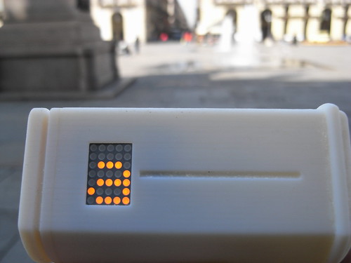
The project here is to find ways to create a simple interface display element, as an experiment in subtractive features — removing things to create less bloat, less confusion. A return to fundamentals rather than feature creep. Not that a 4×5 matrix LED display would necessarily be an end-goal. Rather, what are the limit cases for subtractive design of interface displays? What are the benefits in terms of usability and simplicity and power consumption?
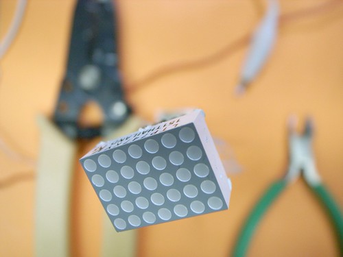
I made another version of the 4×5 matrix display driver using the MAX6953, ostensibly for Slow Messenger, but also possibly for other curious things in the “post-gui” category of explorations. It’s smaller and designed to hold the LED module off of the board so that it’d be possible to have a small setting for the messenger device. I like the idea of a device that’s stalk-like, sort of like these Copic markers I’ve been fond of as of late.
The previous version was like this image, below. You can see that the LED module fits on the board itself, so that mounting the module to fit through some kind of housing would have to take into account the footprint of the entire PCB. That became a bit tricky. I would’ve rather have the LED module at the top of a form like below, but perhaps quite a bit smaller in diameter.
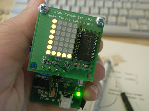
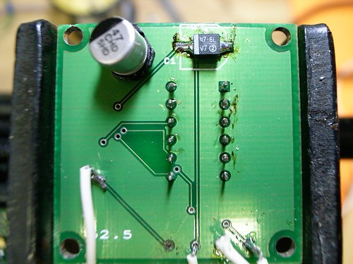
That larger board also had this unfortunate layout issue — entirely my doing. The fatty 47uF capacitor was on the bottom, and the part I used is this ginormous tin can that quite often would get knocked off, or partially knocked off. In the new instance, I managed to find a EIA 3528-21 sized capacitor that’s got a low rectangular profile and put it on top, with most of the other components. I replaced the big thing for the smaller one on this board, above.
Process or Product?

Summing up all the projects that seem to be perpetually in process, I’m beginning to wonder if I’m learning more about process, that is more enthralled with the doing rather than what specifically gets done, especially with the new techniques of design, tools, machines languages.
Should I be paying more attention to the work done or the doing of work?
Here Simon poses some unusual questions to a vendor who basically thought we were asking for the impossible. Ultimately, a good sign. Doing things different, with new set of principles and aspirations means making new processes, not just new products. The implications are on the product itself, certainly, but the process circulates, traveling beyond the single instance.
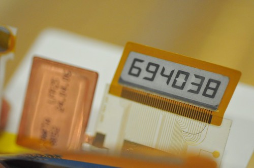
Display
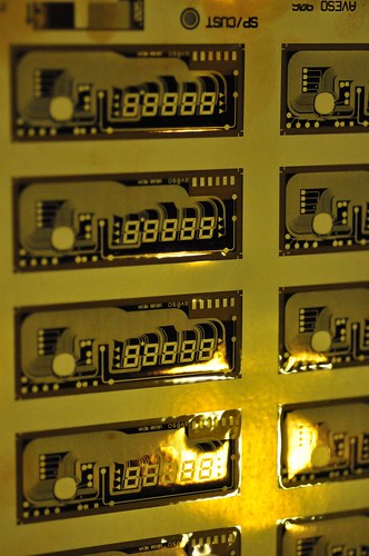
A variety of metal foil etched displays. These are super thin displays designed to be used in things like smart cards and credit cards, or laminated onto some other small, light weight device. Curious how the 8-segment displays feel a bit ancient, like old calculators.
What’s the possible range of interaction and communication that can happen solely with numbers, or even with no display whatsoever. Remember the early Motorola phone displays that only showed digits? Entirely operable, and more than sufficient, considering that telephones once had absolutely no display. Will new crazy, resource intensive features continue to get cobbled onto over-engineered, over-designed devices? Suppose things had to be subtracted from feature lists? What would go first?
Continue reading Display
Interfaces
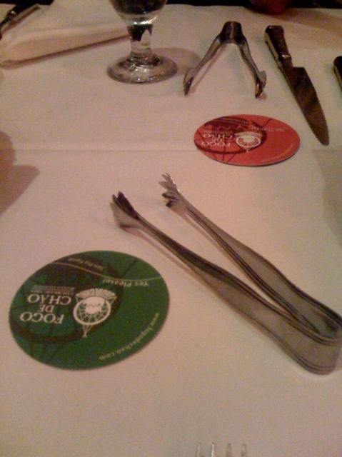
A night out at a fancy Brazilian restaurant in Beverly Hills. The main interface instruments here are the card that can be turned to the green side for “bring me meat” or the red side for “pause..” Judicious control keeps a patron from a serious bout of indigestion. It’s very game-like, this experience. As soon as the card is fliped green, the gaucho’s are on you, skewers brimming with just about every hooved beast imaginable.