The back story of the project tracks back to a conversation with Naimark. Working on the (wrong) impression that a stereo panorama could be created trivially, using two cameras on a rotating, panoramic rig, I was all set to make stereo QuicktimeVRs. Naimark pointed me to a research paper that indicated that such a camera configuration wouldn’t work for a panorama — the geometry is hooey when the two cameras rotate about an axis in between them if you try to capture one continuous image for the entire panorama. In other words, setting up two cameras to each do their own panorama, and then using those two panoramas as the left and right pairs will only produce stereo perception from the point of view at which the cameras are side-by-side, as if they were producing a single stereo pair. You would have to pan around, capturing an image from each point of view, and mosaic all those individual images to produce the stereo.
(I put the references to research papers I found useful — or just found — at the end of this post.)
This is the experiment I wanted to do — two cameras, capturing an image from every view point (or as many as I could) and create a mosaic from slits from every image. That’s supposed to work.
I plowed through the literature and found a description of a technique that required only one camera to create a stereo pair. That sounded pretty cool. By mosaicing a sequence of images taken from individual view points, while rotating the single camera about an axis of rotation behind the camera, you can create the source imagery necessary to create the stereo panorama. Huh.. It was intriguing enough to try. The geometry as described still hasn’t taken hold, but I figured I would play an experimentalist and just try it.
So, the project requires about three steps — the first is to capture the individual images for the panorama, and the second is to mosaic those images by cobbling together left and right slits into left and right images, the third is to turn those left and right images into Quicktime VRs.
After a couple of days poking around and doing some research, I finally decided to build my own — this would save a bunch of money and also give me some experience creating camera control platform for the backyard laboratory.
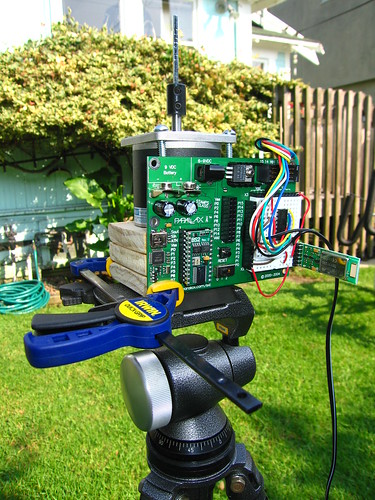
Camera Control Platform
My idea was pretty straightforward — create a rotating arm with a sliding point of attachment for a camera using a standard 1/4″ screw mount. I did a bit of googling around and found a project by Jason Babcock, an ITP students who created a small rig for doing slit-scan photography. (The project he did in collaboration with Leif Krinkle and others was helpful in getting a sense of how to approach the problem. The geometry I was trying to achieve is different, but the mechanisms are the same, essentially, so I got a good sense of what I’d need to do without wasting time making mistakes.)
While I was waiting for a few parts to arrive, I threw together a simple little controller program using a Basic Stamp 2 that could be controlled remotely over Bluetooth. I wanted to be able to step the camera arm one step at a time either clockwise or counter-clockwise just by pushing a key on my computer, as well as have it step in either direction a specific number of steps with a specific millisecond delay between each step.
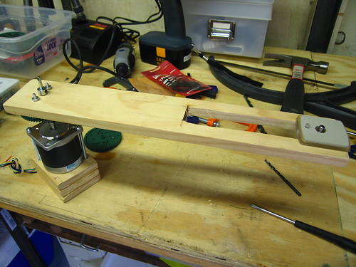
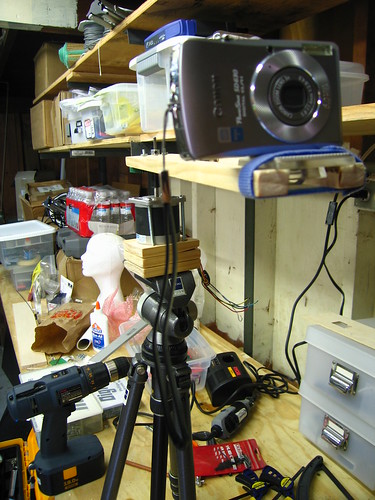
My first try was to use the rig to rotate in a partial circle, accumulate the source imagery and then figure out how I could efficiently create the mosaics. There was no clear information on the various parameters for the mosaics. The research papers I found explained the geometry but not what the “sweet spots” were, so I just started out. I positioned the camera in front of the axis of rotation and set it up in the backyard. I captured about 37 images in maybe 60 degrees. At each step of 1.8 degrees, I captured an image using an IR remote for my camera.
There were any number of problems with the experiment, and I was pretty much convinced that there was little chance this would work. The tripod wasn’t leveled. There was all kinds of wobble in the panorama rig. The arm I was using to position the camera in front of the axis of rotation had the bounce of a diving board. Etc., etc. Plus, I wasn’t entirely sure I had the geometry right, even after an email or two back and forth with Professor Shmuel Peleg, the author of many of the papers I was working from.
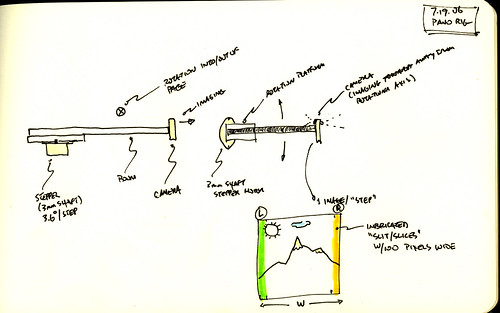
Image Mosaics
With 37 source images, I had no clear idea about how to post-process them. I knew that I had to interleave the mosaics, taking a portion from left of the center for the right eye view, and a portion from right of the center for the left eye view. Reluctantly, I resorted to Apple Script to just the job done — scripting the Finder and Photoshop to process images in a directory appropriately. I added a few parameters that I could adjust — left and right (obviously), the “disparity” — number of pixels from the center where the mosaic slit should be taken, and width of the slit. I plugged in a few numbers — 40 pixels for the disparity and a slit width of 30 and just let the thing run, and this is what I got for the right eye.
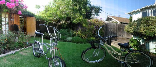
You can see each slit produces a strip in the final image. It’s most obvious because of exposure differences or disjoint visual geometry. (Parenthetically, I made a small change to the Apple Script to save each individual strip and then tried using the panorama photo stitcher that came with my camera on those strips — it comlained that it had a minimum photo size of 200 pixels or something like that. I also tried running it on some other, more prosumer photo stitcher, but I got tired of trying to make sense of how to use it.)
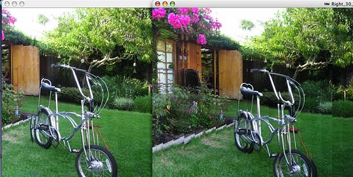
With the corresponding left eye image (same parameters), I got a stereo image that was wonky, but promising.
Here are the arranged images.
I did a few more panoramas to experiment with, well..just to play with what I could do. Now I had the basic tool chain figured out except for the production of a QuicktimeVR from the panoramas. After trying a few programs found a program called Pano2QTVR (!) that can produce a QuicktimeVR from a panoramic image, so that pretty much took care of that problem — now I had two QuicktimeVRs, one for my left eyeball, the other for the right.
Why do I blog this? I wanted to capture a bunch of the work that went into the project so I’d remember what I did and how to do it again, just in case.
Materials
Tools: Dremel, hacksaw, coping saw, power drill, miscellaneous handtools and clamps, Applescript, Photoshop, BasicStamp 2, Elmer’s Glueall, tripod, Bluetooth
Parts: Stepper Motor Jameco Part No. 162026 (12V, 6000 g-cm holding torque, 4 phase, 1.8 deg step angle), Basic Stamp 2, Blue SMiRF module, Gears & Mechanicals, Mechanicals and Couplings, electronics miscellany
Time Committed: 2 days gluing, hammering, drilling, hunting hardware stores and McMaster catalog, zealously over-Dremeling, ordering weird supplies and parts, and programming the computer. Equal time puzzling over research papers and geometry equations while waiting for glue to dry and parts to arrive.
References
Tom Igoe's stepper motor information page (very informative, as are most of Tom's resources on his site. Bookmark this one but good!)
S. Peleg and M. Ben-Ezra, "Stereo panorama with a single camera," in Proc. Computer Vision and Pattern Recognition Conf., pp. 395--401, 1999. http://citeseer.ist.psu.edu/peleg99stereo.html
S. Peleg, Y. Pritch, and M. Ben-Ezra. Cameras for stereo panoramic imaging. In IEEE Conference on Computer Vision and Pattern Recognition (CVPR'00), Hilton Head, South Carolina, volume 1, pages 208--214, June 2000. http://citeseer.ist.psu.edu/peleg00cameras.html
P. Peer and F. Solina:"Mosaic-based panoramic depth imaging with a single standard camera, " Proc. Workshop on Stereo and Multi-Baseline Vision, pp.75-84, 2001 http://citeseer.ist.psu.edu/peer01mosaicbased.html
Yael Pritch , Moshe Ben Ezra , Shmuel Peleg. Optics for OmniStereo Imaging, L.S. Davis (Editor), Foundations of Image Understanding, Kluwer Academic, pp. 447-467, July 2001.
Ho-Chao Huang , Yi-Ping Hung, Panoramic stereo imaging system with automatic disparity warping and seaming, Graphical Models and Image Processing, v.60 n.3, p.196-208, May 1998
Ho-Chao Huang and Yi-Ping Hung, SPISY: The Stereo Panoramic Imaging System, http://citeseer.ist.psu.edu/115716.html
Thanks
Professor Tom Igoe
Leif Krinkle
Jason Babcock
Professor Shmuel Peleg
Panotable Stitcher Program
set inputFolder to choose folder
set slitWidth to 50
set eyeBall to “Left”
set slitCornerBounds to 280
set tempFolderName to eyeBall & ” Output”
set disparity to 0
tell application “Finder”
–log (“Hey There”)
set filesList to files in inputFolder
if (not (exists folder ((inputFolder as string) & tempFolderName))) then
set outputFolder to make new folder at inputFolder with properties {name:tempFolderName}
else
set outputFolder to folder ((inputFolder as string) & tempFolderName)
end if
end tell
tell application “Adobe Photoshop CS2”
set display dialogs to never
close every document saving no
make new document with properties {width:slitWidth * (length of filesList) as pixels, height:480 as pixels}
set panorama to current document
end tell
set fileIndex to 0
–repeat with aFile in filesList by -1
repeat with i from 1 to (count filesList) by 1
–repeat with i from (count filesList) to 1 by -1
set aFile to contents of item i of filesList
tell application “Finder”
— The step below is important because the ‘aFile’ reference as returned by
— Finder associates the file with Finder and not Photoshop. By converting
— the reference below ‘as alias’, the reference used by ‘open’ will be
— correctly handled by Photoshop rather than Finder.
set theFile to aFile as alias
set theFileName to name of theFile
end tell
tell application “Adobe Photoshop CS2”
–make new document with properties {width:40 * 37 as pixels, height:480 as pixels}
open theFile
set sourceImage to current document
— Select the left half of the document. Selections bounds are always expressed
— in pixels, so a conversion of the document’s width and height values is needed if the
— default ruler units is other than pixels. The statements below would
— work consistently regardless of the current ruler unit setting.
–set xL to ((width of doc as pixels) as real)
set xL to slitWidth
set yL to (height of sourceImage as pixels) as real
select current document region {{slitCornerBounds, 0}, {slitCornerBounds + xL, 0}, {slitCornerBounds + xL, yL}, {slitCornerBounds, yL}}
set sourceWidth to width of sourceImage
set disparity to ((sourceWidth / 2) – slitCornerBounds)
if (disparity < 0) then
set disparity to ((disparity * -1) as integer)
end if
activate
copy selection of current document
activate
set current document to panorama
–select current document region {{0, 0}, {20, 480}}
make new art layer in current document with properties {name:"L1"}
paste true
set current layer of current document to layer "L1" of current document
set layerBounds to bounds of layer "L1" of current document
–log {item 1 of layerBounds as pixels}
–log {"—————-", length of filesList}
–this one should be used if the panorama was created CW
–set aWidth to ((width of panorama) / 2) – ((slitWidth * (length of filesList) + (-1 * slitWidth * (1 + fileIndex))) / 2)
— this one should be used if the panorama was created CCW
set aWidth to ((slitWidth * (length of filesList) + (-1 * slitWidth * (1 + fileIndex))) / 2)
translate current layer of current document delta x aWidth as pixels
–set sourceName to name of sourceImage
–set sourceBaseName to getBaseName(sourceName) of me
set fileIndex to fileIndex + 1
–set newFileName to (outputFolder as string) & sourceBaseName & "_Left"
–save panorama in file newFileName as JPEG appending lowercase extension with copying
close sourceImage without saving
flatten panorama
–set disparity to (sourceWidth – slitCornerBounds)
–if (disparity < 0) then
— disparity = disparity * -1
–end if
— this'll save individual strips
make new document with properties {width:slitWidth as pixels, height:480 as pixels}
paste
set singleStripFileName to (outputFolder as string) & eyeBall & "_" & (slitWidth as string) & "_" & (disparity as string) & "_" & fileIndex & ".jpg"
save current document in file singleStripFileName as JPEG appending lowercase extension
close current document without saving
–close panorama without saving
end tell
set fileIndex to fileIndex + 1
end repeat
tell application "Adobe Photoshop CS2"
— this saves the final output
set newFileName to (outputFolder as string) & eyeBall & "_" & (slitWidth as string) & "_" & ((disparity) as string) & ".jpg"
set current document to panorama
save panorama in file newFileName as JPEG appending lowercase extension
end tell
— Returns the document name without extension (if present)
on getBaseName(fName)
set baseName to fName
repeat with idx from 1 to (length of fName)
if (item idx of fName = ".") then
set baseName to (items 1 thru (idx – 1) of fName) as string
exit repeat
end if
end repeat
return baseName
end getBaseName
Stepper Motor Program
‘Stepper Motor Control
‘ {$STAMP BS2}
‘ {$PBASIC 2.5}
SO PIN 1 ‘ serial output
FC PIN 0 ‘ flow control pin
SI PIN 2
#SELECT $STAMP
#CASE BS2, BS2E, BS2PE
T1200 CON 813
T2400 CON 396
Baud48 CON 188
T9600 CON 84
T19K2 CON 32
T38K4 CON 6
#CASE BS2SX, BS2P
T1200 CON 2063
T2400 CON 1021
T9600 CON 240
T19K2 CON 110
T38K4 CON 45
#CASE BS2PX
T1200 CON 3313
T2400 CON 1646
T9600 CON 396
T19K2 CON 188
T38K4 CON 84
#ENDSELECT
Inverted CON $4000
Open CON $8000
Baud CON Baud48
letter VAR Byte
noOfSteps VAR Byte
X VAR Byte
pauseMillis VAR Word
CoilsA VAR OUTB ‘ output to motor (pin 4,5,6,7)
sAddrA VAR Byte ‘ EE address of step data for the motor
Step1 DATA %1010
Step2 DATA %0110
Step3 DATA %0101
Step4 DATA %1000
Counter VAR Word ‘ count how many steps, modulo 200
DIRB = %1111 ‘ make pins 4,5,6,7 all outputs
sAddrA = 0
DEBUG “sAddr is “, HEX4 ? sAddrA, CR
Main:
DO
DEBUG “*_”
‘DEBUG SDEC4 Counter // 200, ” “, HEX4 Counter, ” “, BIN16 Counter, CR
SEROUT SOFC, Baud, [SDEC4 ((Counter)*18), ” deg x10 “]
SEROUT SOFC, Baud, [CR, LF, “*_”]
SERIN SIFC, Baud, [letter]
DEBUG ” received [“,letter,”] “, CR, LF
SEROUT SOFC, Baud, [” received [“,letter,”] “, CR, LF]
IF(letter = “f”) THEN GOSUB Step_Fwd
IF(letter = “b”) THEN GOSUB Step_Bwd
IF(letter = “s”) THEN GOSUB Cont_Fwd_Mode
IF(letter = “a”) THEN GOSUB Cont_Bwd_Mode
IF(letter = “h”) THEN
DEBUG “f – fwd one step, then pause”, CR, LF,
“b – bwd one step, then pause”, CR, LF,
“sN – fwd continuous for N steps”, CR, LF,
“aN – bwd continuous for N steps”, CR, LF
SEROUT SOFC, Baud, [“f – fwd one step, then pause”, CR, LF,
“b – bwd one step, then pause”, CR, LF,
“sN – fwd continuous for N steps”, CR, LF,
“aN – bwd continuous for N steps”, CR, LF]
ENDIF
LOOP
Cont_Fwd_Mode:
SERIN SIFC, Baud, [DEC noOfSteps, WAIT(” “), DEC pauseMillis]
DEBUG ” fwd for [“, DEC ? noOfSteps, “] steps [“, DEC pauseMillis, “] pause “, CR
SEROUT SOFC, Baud, [CR, LF, ” fwd for [“, DEC noOfSTeps, “] steps [“, DEC pauseMillis, “] pause “, CR, LF]
FOR X = 1 TO noOfSteps
GOSUB Step_Fwd
PAUSE pauseMillis
NEXT
RETURN
Cont_Bwd_Mode:
SERIN SIFC, Baud, [DEC noOfSteps, WAIT(” “), DEC pauseMillis]
DEBUG ” fwd for [“, DEC ? noOfSteps, “] steps [“, DEC pauseMillis, “] pause “, CR
SEROUT SOFC, Baud, [CR, LF, ” fwd for [“, DEC noOfSTeps, “] steps [“, DEC pauseMillis, “] pause “, CR, LF]
FOR X = 1 TO noOfSteps
GOSUB Step_Bwd
PAUSE pauseMillis
NEXT
RETURN
Step_Fwd:
‘DEBUG HEX4 ? sAddrA
sAddrA = sAddrA + 1 // 4
READ (Step1 + sAddrA), CoilsA ‘output step data
Counter = Counter + 1
DEBUG ” “, BIN4 ? CoilsA, ” “, HEX4 ? sAddrA
RETURN
Step_Bwd:
sAddrA = sAddrA – 1 // 4
READ (Step1 + sAddrA), CoilsA
DEBUG “bwd “, BIN4 ? CoilsA
Counter = Counter – 1
RETURN

