A mouthful otherwise known as a nice little 3-axis accelerometer from STMicroelectronics with a SPI bus, which makes it handy for interfacing in microcontroller style applications. I picked up one of these in breakout board style from the DIY heros at Sparkfun Electronics to see about its suitability for a DIY pedometer. A bit pricey (single units at $15.95), but its register-based configuration and data reading is pretty cool and eliminates any issues with pulse-width measurements or analog-to-digital conversion. It’s not a slam-dunk replacement for simple projects, but I thought it’d be a good idea to learn more about it, and also learn more about interfacing over the SPI bus.
(See the end of this post for an update on a little problem I had with the device)
Ultimately I want to interface through some Atmel AVR device, but I figured I’d start with the Arduino, since it’s pretty easy to get up and running in that environment.
The LIS3LV02DQ has two interfaces, one of which is SPI. For that, we need four data lines. One for chip select (also known as slave select), one for a clock, one for data in (to the microcontroller, from the slave chip), and one for data out (from the microcontroller, to the slave chip). The idioms in the SPI world vary, as I learned. For instance, here’s a table of how they’re referred to in this case:
| LIS3LV02DQ |
Arduino/Atmel |
Human |
| SDO |
MISO (master in, slave out) |
data in to Arduino from chip |
| SDA |
MOSI (master out, slave in) |
data out from Arduino to chip |
| SCL |
SCK |
clock |
| CS |
SS |
chip select |
Whatever they’re called, the functionality is pretty straight forward. The Arduino/Atmel is the “master” device — it tells the accelerometer chip what to do and when. In this case, “we” (the Arduino) can do things like read or write registers on the accelerometer. These registers configure the chip, tell it to start up or shutdown, read its sensor values, etc. The great thing about SPI is that you can do this all with only a few wires, and the protocol is simple enough that you could write your own firmware to handle it if your microcontroller doesn’t support it in hardware. (Cf Nathan Seidle’s SPI firmware source code example for the PIC.)
Fortunately, the ATMega8 and most of the Atmel ATMega’s handle SPI in hardware.
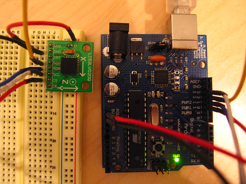
Getting the LIS3LV02DQ up and running is pretty straightforward. I basically wanted to create a simple framework for reading and writing its registers, which means that first I need to hook it up to the Arduino and then initialize the chip and I’d be set. First, hooking it up. Easy peasy.

I’m a bit out of bounds here, because I hooked up the chip to +5V generated by the Arduino. It’s a 2.16V – 3.6V device, ideally. The IO lines can work at 1.8V for logic high. Here I am..in TTL land. Not wanting to destroy the chip, I played around with level shifting but ultimately, for this test, decided that I’d risk TTL logic levels. It’s supposed to be able to take up to +5V, but I suspect the chip isn’t terribly happy with that.
So, here’s what gets hooked up and where:
VDD -> 5V

GND -> GND

INT -> N/C

SDO -> Arduino 12

SDA -> Arduino 11

SCL -> Arduino 13

CS -> Arduino 10
Easy enough. In the source code (available here) are defined a few useful things, such as functions to read and write the registers. The idiom is straightforward. For instance:
// write to a register
void write_register(char register_name, byte data)
{
  // char in_byte;
   // clear bit 7 to indicate we're doing a write
   register_name &= 127;
   // SS is active low
   digitalWrite(SLAVESELECT, LOW);
   // send the address of the register we want to write
   spi_transfer(register_name);
   // send the data we're writing
   spi_transfer(data);
   digitalWrite(SLAVESELECT, HIGH);
}
Performing the actual transaction over the SPI bus is handled largely in hardware. The ATMega8 has a register called SPDR that, when written to, begins an SPI transaction. Once you start a transaction, you have a choice of two ways to handle it. One is to simply wait around until the transaction is over, indicated by the SPIF bit being set. The other is to set up an interrupt vector for this bit, which will result in a designated function being called when the interrupt occurs. We’re not doing all that much, so it’s easier to just sit around and wait for the data rather than set up the interrupt vectors. The way you do this is to loop until the SPIF bit gets set.
char spi_transfer(volatile char data)
{
  /*
  Writing to the SPDR register begins an SPI transaction
  */
  SPDR = data;
  /*
  Loop right here until the transaction is complete. The SPIF bit is
  the SPI Interrupt Flag. When interrupts are enabled, and the
  SPIE bit is set enabling SPI interrupts, this bit will set when
  the transaction is finished. Use the little bit testing idiom here.
  */
  while (!(SPSR & (1 << SPIF)))
  {};
  // received data appears in the SPDR register
  return SPDR;
}
The spec sheet for the LIS3LV02DQ has specific instructions about reading and writing registers and what all of the registers are for, and other important stuff, like clearing bit 7 of register name to indicate that what’s happening is a register write. I recommend reading it carefully to understand some of the nuances. But, it’s pretty easy to work with, all in all.
My main loop() simply reads the registers that contain the X, Y, and Z axis values indicating acceleration along those vectors. The value that are generated by the LIS3LV02DQ represent a range of acceleration readings between -2g and +2g (the device can be configured to read +/-6g as well.) The registers contain either a high or low order value, so there are actually six registers to be read, two registers to compose a 16bit value. Although, actually, the default range of precision is 12 bits, with the most significant four bits, in this mode, containing the same value as the 11th bit, which effectively is the sign (+/-) of the data.
The values that are generated, once formed into a 16 bit word (with 12 significant bits) is such taht 2g = 2^12/2 = 2048, which means that 1 x gravity should be a value of 1024. If you place any of the chip’s axes normal to the ground, you should see the value 1024, or thereabouts (possibly -1024).
Calculating a reasonable acceleration in the normal, human units (meters per second per second), you’d multiply the value by 1/1024. You’ll need to scale the values into the long datatype range, I’d suspect, as you can’t do floating point math. And your 9th grade physics will tell you that:
velocity = a * t (meters/sec)
distance = v * t (meters)
So, you would sample the acceleration along an axis in the direction of motion and use an average of the acceleration over the sample period to calculate velocity.
void loop()
{
  byte in_byte;
  int x_val, y_val, z_val;
  byte x_val_l, x_val_h, y_val_l, y_val_h, z_val_l, z_val_h;
  // read the outx_h register
  x_val_h = read_register(0x29); //Read outx_h
  // high four bits are just the sign in 12 bit mode
  if((x_val_h & 0xF0) > 0) {
    Serial.print("NEG_X");
  }
  // comment this if you care about the sign, otherwise we're getting absolute values
  x_val_h &= 0X0F;
  //Serial.print("x_h="); Serial.print(x_val_h, DEC); Serial.print(", ");
  // read the outy_h register
  x_val_l  = read_register(0x28);
  //Serial.print("x_l="); Serial.print(x_val_l, DEC); Serial.print(", ");
  x_val = x_val_h;
  x_val <<= 8;
  x_val += x_val_l;
  // the LIS3LV02DQ according to specs, these values are:
  // 2g = 2^12/2 = 2048
  // 1g = 1024
  // if you use the sign, that gives a range of +/-2g should output +/-2048
  Serial.print("x_val="); Serial.print(x_val, DEC);
  y_val_h = read_register(0x2B); //Read outx_h
  y_val_l = read_register(0x2A); //Read outx_l
  y_val = y_val_h;
  y_val <<= 8;
  y_val += y_val_l;
 Serial.print(" y_val="); Serial.print(y_val, DEC);
  z_val_h = read_register(0x2D); //Read outz_h
 // Serial.print("z_h="); Serial.print(z_val_h, DEC); Serial.print(", ");
  z_val_l = read_register(0x2C); //Read outz_l
 // Serial.print("z_l="); Serial.print(z_val_l, DEC); Serial.print(", ");
  z_val = z_val_h;
  z_val <<= 8;
  /*Serial.print("z_h_<<8="); Serial.print(z_val_h, DEC); Serial.print(", ");*/
  z_val += z_val_l;
  //long g_z; // say approx 100 cm/s/s
  //g_z = z_val * 10 / 1024;
  Serial.print(" z_val="); Serial.println(z_val, DEC);
}
Update: I started having problems with the device when I had more than one SPI device on the interface. The problem revealed itself when the LIS3LV02DQ would send back erroneous data if it was not the “first” in the parallel chain of devices along the SCL net. So, if I went from Arduino pin 13 to the LIS3LV02DQ SCL, then to another device’s SCL, it would work fine. But, if I went to another device’s SCL “first” then to the LIS3LV02DQ, it would break sending back 0x30 or 0x38 for the WHO_AM_I register rather than the expected 0x3A. Or, if I had a test lead connected to the LIS3LV02DQ’s SCL and touched the lead, it would also send back erroneous data. After some back and forth with tech support at ST Microelectronics, I found out to my embarrassment that I was using the wrong SPI mode. I should’ve been using mode 3 (CPOL = 1 and CPHA = 1) and I was using mode 0. I made corrections in the code.
Here’s the full source code for interfacing to the LIS3LV02DQ using an Arduino
LIS3LV02DQ sensor available from Sparkfun Electronics
Arduino available from Sparkfun Electronics
Arduino Board Main Site
Why do I blog this? Notes on how to get this accelerometer to talk to the world.


 At
At 


