Weekending 03032012

In Switzerland, after an hectic week with Lift12, Nicolas went back to design workshops with students. Last Monday and Tuesday, he gave a course in interaction design at the Geneva University of Arts and Design and supervised the last details of the Urban Games project with Etienne Mineur and Daniel Sciboz. The workshop, which started last fall, is now completed with eight videos that are going to be shown at the Playtime exhibit. They describe different scenarios for location-based games using the city as a game board, we’ll try to show them on this blog as soon as it can be made public. Overall, this workshop was meant to explore different game mechanics at the city level and how to go beyond existing archetypes in this domain.

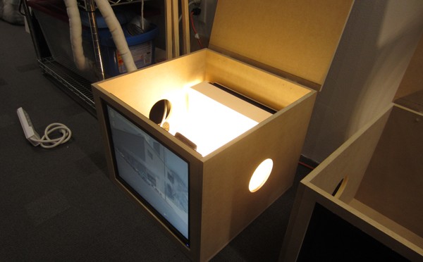
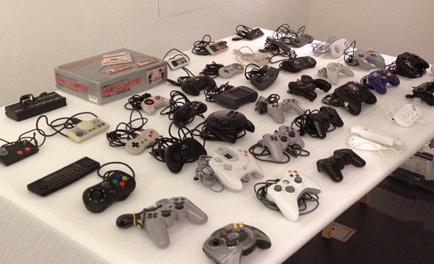
Also, the very same exhibit will feature the game controller collection and Nicolas and Laurent Bolli had to check the final arrangements for the pads to be shown. The piece will consist in a big cabinet with 42 joypads (41 actually since the Kinect doesn’t have anything) to describe the iterative evolution of game pads over time. This portion of the collection will be part of a section called “Bodies and Minds”:

“game pads have been the traditional interface between the player and the avatar, the thread that entangles both bodies. In recent years, though, both the video game industry and independent artists and researchers have presented new innovative ways to strengthen the role of the body in game interaction. From Nintendo’s Wii and Microsoft’s Kinect to more experimental corporal interfaces that play with notions of control and even pain, the future of game interaction will, no doubt, involve our flesh and skin in unexpected ways.”

At the end of the week, he went to Lugano (the swiss-italian part of Switzerland) for a talk about user research in design and to discuss potential workshops in this interaction design program.

Last week Julian spent a bit of time running the Marshall Stack project, which meant lots of semi-hands-on/semi-hands-off tasks. In the studio a very lovely little film was made to help communicate the project. As these things go, it wound help helping the core DRI’s for the project as well as those who are outside of it or just coming in from the outside and have no clue as to what we were doing. This is one direct area where Design Fiction film serves an extraordinarily useful role — it helps communicate in a way that words and discussions often cannot, or can once someone has seen the experience in a little film. It’s been very useful and well-worth spending about three-quarters of a day to produce. I’m excited about the development pace of Marshall Stack. The distance between the decision to do it, actually starting it formally, and our deadline has been aggressive — especially starting and the goal line. There’s something about the project and the way it is framed and the constraints put upon it to get to the core part of the UX — to focus ruthlessly on that core — that has some lessons to be shared post-launch. As well as some general observations about the nature of working on a rapid development project with a small team, where people sit, and how the collaboration unfolds that I’m looking forward to sharing when we’ve finished this up. I’m deliberately being mindful of the activities within the project and taking lots of notes so as to better produce a story about how you do this sort of advanced designing. I think that the core of the story will be about advancing design and not only the material design things we did along the way. Marshall Stack is one of those projects that has lessons both within and outside of it. By that I mean that it is attempting to advance what an organization does, but do so by doing the advanced, unexpected, weird things — but those things are actually viable things, not just exercises or substitutes for an unknown future-disruptive thing like a Lego brick or the generic stand-in, “the widget.”

Anyway..

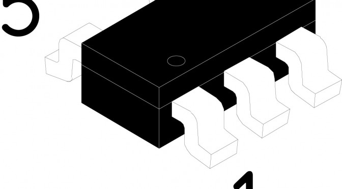
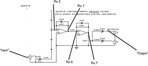
Later in the week, I went on a one-day trip to San Diego to scope out some heavy equipment for the model shop — specifically for the electronics bay. We’re looking at Pick-n-Place machines so we can rev-up the rapid in rapid prototyping. (Now, it’s a daunting task to populate boards with SMT components that like to fly away and requires hours and hours of uninterrupted time to accomplish. The hours-and-hours is the operative term and right now I’m the only electronics guy.) A pick-n-place machine could be just the thing to make that job take on the order of tens of minutes rather than many hours/entire days — even for small numbers of multiple boards. (And we got a weird book — doesn’t matter but it’s called “Shatner Rules” — signed by Mr. Shatner himself..a perk of the APEX 2012 Electronics Manufacturing Trade Show!) Now if we can just figure out where this new robot will go in the already crowded shop..

At the end of the week, Julian and Nick (not Nicolas) met in Tempe Arizona outside of Phoenix. We were there to run a workshop on Design Fiction where we aspired to make a few little vignette-y films about the near future of the corner convenience store. This of course was based on the observation that many great innovations over the course of human history find their way into your corner convenience store — fire, aspirin, for example. Our question for the Emerge event was to project that observation into the future when all great things no matter how fancy or expensive originally, wind up with the net present value of 99¢ or 3 for $1.

Up North, Fabien went to San Francisco for a talk at Strata, the O’Reilly conference about big data and “building a data-driven”. He presented several projects conducted by the Laboratory and then took off for Maui for a well-deserved break.

Weekending 12022012

This week in Barcelona started with the pleasure of having Quadrigram making the cut of the finalist of the Strata 2012 Startup Showcase. The tool is a couple of weeks away from seeing the light and the teaser video is now online. At Strata, I will present the tool with my friends at Bestiario right after my session on Sketching with Data.

On the invitation of Claro Partners to present the lab, I took the opportunity to present my experience working with network data, particularly focusing on the methods we employ to help innovate in the domain of ‘big’ data. Have a look at the slide deck: it starts with a reference to Napoléon Bonaparte ‘Un bon croquis vaut mieux qu’un long discours’, goes through the uses of sketches as part of any creative work exemplified by Le Corbusier, and concludes with Picasso and the art of sketching.

Okay. What else? In Los Angeles, we used a solder paste stencil for the first time. Impressed. Good stuff. Definitely worth $25-$50. You can tell in this video I haven’t used solder paste in awhile..I forgot to put the proper hot, hot air on so I’m basically just blowing balmy air on the board. More practice, again. I have to say, the stencil is definitely a time saver. Although, I’m still going to get a big-ass pick ‘n place machine cause that’d make it even faster to get boards done. ((That’s EarFreshener up in that video, by the way.))


Nicolas came to town on Saturday and Sunday we went to the crazy flea market at the Pasadena Coliseum, home of the Rose Bowl. We found weird things and Nicolas found a fantastic mint-condition Polaroid in its crushed red velvet case. Lucky old salt. Prior to that, his week was focused on both phone call with Lift12 speakers and the final presentation for the head-mounted display project, which went fairly well. Results from this field study are kind of secrets so far but there will eventually be a publication about that.

This Is What I Sent — The Ear Freshener PCB Design

Here’s the current PCB CAD for the Ear Freshener. It’s sorta got two sides, but on the top I basically have a carrier for another board that contains the audio codec device. The components around it are all the brains that control track selection from the potentiometer/knob — that people will think, hopefully, is the volume knob, but actually it isn’t.

The gag/provocation is that knob. It’s an audio thing with a knob..but the knob isn’t an on-off thing. Rather, it’s some kind of semantic intensity knob. You turn it “up” and you get more-of. You turn it “down” and you get less-of.

There’s also a spot to hook up a little button. The button switches the Ear Freshener sound idiom. So you can go through the seasons; or cities; or airports.

((We should figure out a good name for the gag/provocations that we always build into our little devices.))

To do this, I’m probably a little over-engineered, maybe. Maybe not. I use two Atmel Attiny25‘s that basically do the track selection through a data port control on the audio codec. Basically counting in binary, with the track selection one doing the low-order bits and the high-order bits selecting the sound idiom you’ll be freshening your earballs to.

There’s also a bit of circuitry for a step-up regulator. I want to run this off of a single, readily available battery cell — AAA or AA. I’m over USB charging for the time being. At least now. The extra crap you need is a headache. Sorta. I guess I just wanted to get back to that thing where your audio devices take a battery. Not that I want more batteries in the world, but the rechargeable ones? They’re fantastic nowadays. Lots of capacity.

You’ll notice there’s a bunch of nothing on the right. I put that there for mechanical mounting of a battery holder for now. I just didn’t want the battery dangling off in nowheresville. This way I can double-sided sticky tape it to for testing and carrying around.

That’s the deal. I sent off the data to AP Circuits for the first time. It was about $40 with shipping for two boards. The boards are about 2.1in by 2.3in, so sorta small. There was a bit of back and forth to get the data they needed, especially for the board outline. This always ends up being something I leave out — my CAM Processor script doesn’t have that layer built in as output. Need to look into that.

Why do I blog this? I need to keep going on making logs of activity for the various projects that go on here, even if it’s a quick note.

Weekending 21012012

Fabien and Nicolas went to Madrid for a workshop at BBVA innovation about Smart Cities. Organized by Urbanscale (and more specifically by Jeff Kirsh, Adam Greenfield and Leah Meisterlin), it focused on opportunities to use networked data for the client. It basically followed up on the previous work we have done with this bank last year.

The workshop went well, with a combination of short talks, field observations (qualitative and quantitative) and discussions. This workshop was followed by an open session entitled “Beyond Smart Cities” at BBVA’s Innovation Center, with Adam Greenfield, myself (Nicolas) and Kevin Slavin. My slides are on Slideshare. There’s a write-up of the event at the following URL. As described by Kevin on his tumblog, “As surely as it feels like a movement has a name (“Smart Cities”) it also feels like the critique of said movement is collectively more articulate and persuasive. Now the key is to find language to describe what it should be, to go beyond popping the balloon and figuring out what the party really needs.“.

Here in Los Angeles Julian has been hard at work puzzling over an incredibly simple problem of making a little audio device called an Ear Freshener avoid having a power switch and a volume knob. He thinks the solution was intimated by a generous comment poster who told him to slap a couple of transistors in strategic locations in the circuit. So he tried that. It seems to make sense. Hopefully it won’t destroy everything.

Related to this were discussions about the principles behind/between things that make sound — such as sound should just come out of them, rather than be all fussy with settings, configurations and network connections. And that tied into an ongoing thinking thing about latter day considerations about “simplicity”, “one thing done well” and skinny Williamsburg/Brick Lane 23 year olds with full beards who’ve done nothing to deserve a full beard but rock Holgas and fetishize film/vinyl/casette tapes fixed-gear bikes and the like. Thus, we’ve been working on a short essay on the topic of the Cult of the Analog Cult. Or something like that.

Meanwhile, on the East side of L.A. Jayne (with Kickstarter funding in hand) has been getting back to making new Portals. They’re still in the physical draft/sketch phase of things but making the upgrade from end-table-foam-core to mdf feels quite satisfying. The insides are still very rough and she’s still getting started with hooking up the magic/technology bits, but at least now a pair of Portal boxes exist in the world, ready to be filled with interactive goodies.

Continue reading Weekending 21012012

Sound Should Just Come Out Of It

I think going forward I should do a better job of talking around what we’re working on from a technical point of view, until such time as it’s okay to talk about what we’re doing from a principles, rituals and practices point of view. And, also — sometimes in the thick of a design-making-schematic-and-hot-air-baking fire-fight, I do something that I”ll likely have to do again, but without a good, thorough practice of writing things down to remember I, like..forget.

Here’s the thing. I’m making a little tiny audio device. It’s tiny and meant to be simple to use. Like Russell taught me — the thing about audio? You should be able to just turn it on and sound comes out.

I like that rule. That’s what radios used to do before all the knobs, settings, configuration preferences, long vertical scrollable lists and Internet connections fucked things up. You turn the little serrated rotary dial and *click* — radio sound. At worse? Static. But sound started. No swipes. No multi-finger gestures. No tyranny of the 10,000 hours of music & sound in the palm of your hand..and no idea what you want to hear.

There’s something lovely about that that is just pragmatic from an IxD and UX design point of view. I’m not being nostalgic.

So — translating this principle and making it active and not just a sweet, essentialist sounding statement into the guts of the things we’re making, I spent most of yesterday pondering how to make Ear Freshener exhibit and embody and be an exemplar of this design rule. Even to the point of saying, okay..no on-off switch.

Huh?

Yeah, well — the Ear Freshener has the advantage of being a plug-y thing. No speaker. It’s an intimate audio headphone thing. You’d only expect sound out of it when you plug in your headphones. Otherwise — it’s just a little thing that’s quite opaque. There’s only the tell-tale 3.5mm hole that indicates — audio/sound/plug-in-y-ness.

So — simple enough. I decided that plugging-in should equal sound-coming-out. That means that the plug action should turn the actual electronics on. In the world of audio connectors, CUI, Inc. is the go-to operation — along with what I’m sure is a thriving, teeming “ecosystem” of knock-off competitors who may even produce a superior product. They make all sorts of audio connectors for the world of audio devices. There’s a collection of them that have more than the three connectors that are necessary for a Tip Ring Sleeve style stereo audio signal, including the SJ-43614 which is a 3.5mm plug with four signals. The extra one switches from floating (not connected to anything) to ground (or the “sleeve” of the connector, which is normally connected to ground) when you plug a plug into it.

Brilliant. Something changes when you plug the plug into the SJ-43614. One of those signals on that connector gets shorted to the GND rail of the circuit.

Now..what to do with that state change in order to turn the whole circuit on and make sound come out of it with no fuss, no muss.

I pondered and scritched and screwed my face and looked for the answer somewhere on the ceiling over there. I thought of lots of overly-complicated things (as it turns out..in hindsight..) like using a low-power comparator to activate the chip-enable pin of the little 200mA step-up switching regulator I’m using so I can run the circuit off a single 1.5V battery cell.

In that over-designed scenario the NCP1402 step-up regulator is effectively the power supply for the circuit, which wants at least 3.0 volts to operate properly (and draws about 40mA). I can get an NCP1402 hard-wired to output 3.3v, although I may get the 5v version to have a bit more headroom with volume. In any case, this chip is fab cause you can take a little 1.5v cell and it’ll tune up the voltage. Of course, it’s not 100% efficient. Nominally, it’s about 80-ish% efficient at 40mA. So..you lose a little, but you can’t get something (5v) for nothing (1.5v) without giving up something in the trade.

NCP1402SN50T1 efficiency versus output current


So, I have a 1.5v battery of some sort which sits behind the NCP1402. The NCP1402 has an active high chip-enable (CE) pin that turns the chip on — effectively powering the rest of the Ear Freshener circuit. In my overly-complicated scenario, I figured I could use a comparator to sense when the 3.5mm plug had been plugged-into because that one switched pin would go from floating to ground. If I had a simple little 10k resistor between the positive 1.5v side of the battery, the comparator inputs could go on either side of that resistor, with the IN- of the comparator on the side of the resistor that would get shorted to ground when the plug is plugged in. And then the IN+ of the comparator would go on the side of the resistor that is connected directly to the positive side of the 1.5v battery. When the plug goes in, the IN- of the comparator goes to GND, the 10k resistor has a little, negligible-y minuscule current draw and the voltage difference between IN- and IN+ causes the output of the comparator to saturate to pretty close to IN+, or +1.5v. The NCP1402 chip enable would trigger (specs say anthing about 0.8v means “enable” and anything below 0.3v means “disable”) and the whole thing would turn on.

Click the image to expand it and make it easier to read. This is the lousy, over-designed circuit.


How convolutedly and moronically clever is that, especially when you stop to think (as I did, after proudly building the schematic) that you could just use that pin from the plug shorting to ground as a way to close the GND rail of the whole circuit. I mean..if you disconnect the NCP1402 from GND, it should turn off. Basically, it’d have no complete, closed, power supply circuit. It’s as if you pulled the battery out — or half of the battery out. Or ripped out the ground wire.

Anyway. It was clever to get all busy with a comparator and stuff. Simple’s better, though.

This is the simple, no-brainer one that eliminates the need for several additional components.


That’s it. I like the principle and I like even better the fact that I can translate a lovely little design principle into action — materialize it in a circuit that exhibits a fun little unassuming behavior. I can imagine this’d be a bit like wondering if the light stays on in the fridge after closing the door, you know?

So sound stops coming out, the circuit powers down and you no longer need an on-off switch. Stop listening? Turn off. So much nicer than long-press, id’nt it?

Why do I blog this? Cause I need to capture a bit more about the production of this little Ear Freshener-y gem.

Update


Here’s my update on the power circuit. I hope it works. I added two transistors in place of the comparator. The idea here is that the transistor on the right would switch the CE of the step-up switching regulator. When the base goes low — i.e. when the 3.5mm plug is plugged in — the switch opens and CE gets switched to roughly VBATT and enables the step-up regulator. For the transistor on the left, plugging in opens the transistor and VBATT gets connected to the step-up regulator and it, like..steps-up VBATT to VCC. When the plug gets pulled out and floats at VBATT, the two transistors saturate and are on. So on the right, CE is at Vce or effectively ground and shuts the step-up regulator off. The transistor on the left does similar and VBATT drops over R6 and VBATT_SWITCHED is at GND and there’s no longer any supply to step-up, even if the step-up regulator were enabled.

That’s the idea.

We’ll see. I haven’t computed the values for the discretes around the transistors as of yet.

Related — I’ve just sent off the PCB to get fabricated. It’ll be a 2-off prototype. I’m using AP Circuits for the first time because my usual go-to guys Gold Phoenix are off for the Chinese New Year and I need to get this done for some building & testing next week.


But I think I mucked up the CAM data files I sent them, which appear to be slightly different from Gold Phoenix. They want other stuff, like the NC Tool list which I’ve never sent to Gold Phoenix. I guess we’ll see what they say.
Continue reading Sound Should Just Come Out Of It

Weekending 12102011

On my side (Nicolas), the week was split between consulting (a workshop about social gaming in France) and different teaching gigs. One of them, at the Swiss Institute of Technology in Lausanne (EPFL), is a year-long course about designer’ approaches and tactics for engineers. We address various methods ranging from user research to prototyping. Given that the course lasts 3 hours per week and that we have not access to any studio facility, we have to do things in a pretty low-fi way. It’s challenging but very intriguing at the same time. This week the course was about mock-ups in interaction design and the role paper could play in this. Inspired by the Post-it phone approach developed by Matt Cottam at CIID, the students had to produce a quick and dirty mock-up of their project. The idea was that they had to rely on the results of the previous courses (field research, brainstorming session).

It was actually the first time I ever tried this approach and it went rather good. Using paper like this was both fun and engaging, especially because I asked students to act out the use of the device; one student being the computer (making audio sounds to mimick the interface), another being the user. This role-play was important as it enabled a “critique” phase afterwards during which anyone of us had to write down the pros and cons of the proposed system and present this to the user and its “computer”. Back to the laboratory, this ideas got me into listing a whole set of workshop activities and tactics that we can deploy on projects.

Over on this side of the world (Julian) most of the work was focused on getting some bits of technology to play together for the Ear Freshener concept for Project Audio. There are some fiddily bits that mostly had to do with not having played with Atmel 8-bit microcontrollers for a long while and their AVR Studio 5 having gone to edition 5 from 4, which meant upgrading it, which meant upgrading the other thing, which meant upgrading that other thing, which meant upgrading that one other thing, which meant upgrading Windows, which meant upgrading the thing that one other thing that didn’t want to upgrade itself, which meant planting my face in both palms and cursing lots of things. I’m also using this new debugger device — the AVR JTAGICE 3 — which as best as I can tell is a smaller thing than the huge AVR JTAGICE that came before it but otherwise the same. That’s finicky, too — but the single wire debugWIRE protocol for debugging is quite nice, although it can get you stuck in debugWIRE unless you know about the one little buried menu item to force the DWEN fuse to reset. That was another thing. I’ll have to do a little action-item post about the process of working with these new tools, for the tool-y people out there.

The result? Thursday night we had a functioning Ear Freshener (or should I say — EarFreshener?) in prototype mode, which you see above. It has a proper continuous adjustment knob that you might think is volume, but you’d be wrong. We went with the microcontroller to control the audio channel selection rather than writing code for the other device, which we’re definitely less familiar with. The extra chip and such won’t make a difference in scale or fitting or anything like that. The goal for this week is to produce some more audio and get Ted or Nick or someone to sit alongside and think about more of the IxD for the thing.

That was good progress by Thursday evening so I gave myself the rest of the week off and went to the Salton Sea for the afternoon.

That’s it.

Continue reading Weekending 12102011

Weekending 11272011

Whoa. Last week? Well — it was a short one. It was quiet ’round the studio. Which meant that quite concentrated bits of work could happen.

Advanced Projects Tippy-Top News — the Project Humbo set is done for Project Audio in the Advanced Projects Wing. That’s work, work. By “done”, I mean — built and tested. They work. The studio will hum with the sounds of a new wave of radio audio micro-local broadcasting. The world’s been turned upside down. RCA/Victor win! McCaw Cellular never was in this little parallel universe. More later.

Advanced Projects Near-The-Top News — major breakthrough with the Project Ear Freshener for Project Audio. I took a blurry little photo which is just a blur cause I think I was tired and the light was lousy. And, anyway — it’s a small breadboard with some bits on it. Imagine. As it turns out, poor documentation was the cause of the snags and hassles. And fortunately technical support was forthcoming and informal and conversational, which likely has to do with the outfit that makes the chips being nice and small. But — I’ve been spoiled by the Arduino kits. They’re way easy. I suppose I shouldn’t expect much clarity and convenience for a chip that basically winds up in stuffed talking teddy bears and the like. ((We’re not making talking teddy’s, by the way. Much better things.)) I have a little draft post of some of the technical gotchas we faced just to document the ways of working with this chipset.

Laboratory Tippy-Top News — Jayne Vidheecharoen has become more formally and less informally a part of the studio. You’ll notice the little post with an introductory Q&A with Jayne. She’s a clever creative with a lovely playful sensibility. There’ll be some fab projects and provocations in the future. I recommend you look closely at Jayne’s prior work, especially Customer Service Romance and Souvenirs From The Internet.

And in Just The News, came across an interesting article in the Harvard Business Review, which finds its way into the kitchen and livingroom of the studio but I don’t normally read it. I think I was waiting for the microwave to bleep at me and starting absent-mindedly flipping through it. There was a curious article on what makes a functioning, innovative, creative team. It came down to less management and more trust and some mechanisms for individuals setting their tasks and objectives based on a simply stated, tangible overarching organizational goal. That feels quite a bit like what happens in the Advanced Projects studio. The article is called First, Let’s Fire All the Managers.

Continue reading Weekending 11272011

Varieties of Controls

Never would’ve thought how particular a fella could get about the action of audio controls. I’ve collected an assortment of potentiometers for the audio mixer project. From well-dampened to action that goes tick-tick-tick with detents. The red one in the foreground? That’s an optical encoder that continuously spins — no stops. It might be a bit of a control fetish, but the action of these things matters. Even in an era of touch, click and very screen-y interactions tactility and motion matter. Which raises a little concern — not doubt, just concern — about going hog-wild with gestures.

Why do I blog this? Things are moving forward with the audio mixer. Slower than expected; unexpected things in and around the studio plus upcoming travel preparations and a shift-in-time to make the U.S. Labor Day holiday happen for me this Friday. Downtime and uptime. Sending the PCB off any minute now..
Continue reading Varieties of Controls

More Audio Experiments

Well — about half the day..actually more! Spent trying to get a rudimentary single op-amp circuit functioning. I mean…maybe I’m a bit distracted and maybe in a rush. Either way — this should be going easier.

I ended up stripping everything off the breadboard and starting fresh. I even went back to an LM741. My biggest confusion through all this was the split-rail supply and how to hook it up. I made a simple circuit using a TLE2426. But then..I was a little flumuxed about what to do with the VGND signal. But I figured it out in between bouts of frustation and lots of shrugging. Basically, the -V of the TLE2426 circuit goes to the “GND” or negative supply of the op-amp. Turns out — the VGND of the TLE2426 goes to “ground” of the rest of the circuit. The +V and -V from the TLE2426 goes straight to the supply terminals of whatever op-amp you’re using.

*shrug

Well — I sorted it out. Just stayed a bit late Friday after helping make a little film. Once things quieted down I could focus on debugging the circuit. I started from scratch. I basically wanted to go back to the rudiments. Build an inverting amplifier; a non-inverting amplifier; and a circuit I could use as a pre-amp for a microphone or something. And then just put signals up on the scope to see what sort of power I’d need in order to support mixing and amplifying signals without distortion.

I tried with two different op-amps — the LM741 and the LM348. I don’t know which is better than the other. They look like they perform similarly. The upside of the LM348 is that it comes dual in an 8 pin package. I tried them both in inverting and non-inverting set ups.

I’m working with all this on a breadboard cause, basically I’m rewiring stuff left and right and I haven’t worked with op-amps since college and I’ve been mucking up bad enough that I didn’t feel comfortable at all spinning a PCB even though these circuits are stupid simple.

Here’s a comment.

The chip in the middle of the breadboard up there is the TLE2426 which is providing the split-supply for the op-amps. Without that, the circuit will clip any signal that falls below the supply rail. That was something I wanted to test a bit empirically, so I tried to see under what parameters they would clip a signal.

In the image below I found that a 4.08v signal peek-to-peek, the op-amp would clip the signal if the power rail was 6.4v or less. That 4.08v signal was produced from the maximum power output on a MacBook Pro with the signal being a 440Hz sine wave.

Here’s that signal run through the LM358 set up non-inverting. See? It’s not inverted.

And above — the LM741 inverted.

Then I tried the LM358 with a x1000 factor amplification to see how well it’d do as a microphone pre-amp. Curiously — none of the ragged old little lavaliere microphones I had around seemed to work at all. So..I used my hipster headphones as a sorta microphone by “listening” to the signal from the headphone jack with the headphone draped over a crap speaker I use to listen to music in the studio.


So — here are the schematics I used. The basic deal.

Well..I feel a lot better that I got this stuff working. I mean..it was sorta nuts last week trying to make that mixer and just having everything go bonkers. I think maybe it was important to just get back to basics and build up from basics rather than using someone else’s circuit design and hoping for the best.

What this helped me do is figure out what I want the special weird mixer thing to do. It needs two microphone inputs — so two preamps for mic-level signals from the two microphones for capturing ambient audio. It should have two stereo inputs for two different sources like a music player and something else, like a phone. The mic inputs should be able to pan from left to right. I think all of these signals should also be able to go through an “effects send” to do fun things to them — maybe even phase them a bit to do some experiments with spatialization. I think there should be one other mono input for signal generation — you know..for annunciators and maybe synthesized voice or something. So — that’s three mono inputs and two stereo inputs. The stereo inputs should also be able to have their balance adjusted, I think.

I think that’s the rough spec. Onward.

Continue reading More Audio Experiments

LM358 Op-Amp Issues

Audio Mixer Schematic

Should be simple…here’s the test circuit. It’s derived from the multi-channel mixer below. I’m just testing the circuit. It should basically pass through the one input signal perhaps with some attenuation. Instead, it distorts it all to hell-and-gone. Any ideas?

So — back to hammering and less yammering. I’m trying to build a small, portable, DIY audio mixer. Thus far — I’ve found nothing off-the-shelf that meets my, you know..specifications. There are lots of inexpensive and rather expensive field mixers but those are honking things with gigantic XLR inputs for proper microphones. I want about two 1/8″ stereo inputs, and maybe two or three 1/8″ mono inputs. I want to mix a few things and I want the whole thing about the size of deck of cards or something small like that. The only thing I can think to do is to build it.

Plus..we like to build things.

It should be simple but I’m about a decade out of analog electronics. I used to be able to debug op-amp circuits but not any more. And back when I could they didn’t have the internet the way they have now, so I’m sorta putting it out there with as much evidence of the problem as I can muster.

I built the circuit you see above using an LM358 op-amp. Seems like a reasonable go-to unit to build around and many op-amps, as I recall, are generic enough that I feel like it should work in this circuit. (But, I’m prepared to be wrong.)

The problem is that the signal gets super distorted right from the get go.

I’m using my MBP to generate a signal using Max/MSP. It’s just a 1kHz pure tone — a sine wave. The output comes out of the computer, right? Max/MSP generates the signal to go out on one channel and that’s what I feed into my circuit.

Basically — it gets distorted, even at the input. Check out the signal at pin 2 (the + on the left-most op-amp) — it’s what comes after a resistor and capacitor from the input signal. Why’s it so clipped even before it gets processed except for a couple of discrete components? I think that’s the heart of the issue cause the signal doesn’t even touch the op-amp?

So — obviously screen shots from my scope. The top cyan trace is the audio signal I injected into the circuit. It’s a 1kHz sine wave generated from Max/MSP and output over my MacBook’s audio output. It’s about 280mV P-P.

Pin 2 – Basically the input signal after a resistor and capacitor. It’s like..totally clipped there. Why it’s clipped between the raw signal and the input on pin 2 is baffling me. I’ve been so far from analog circuits for so long..I’m just not even sure why putting it on pin 2 alone clips it this way.

The output from the first Op-Amp in the mixer circuit..looks kinda hinky..worse than the input on pin 2.

Things only get worse from there. The output of the first op-amp looks like worse crap. This is basically the op-amp processing one signal and mucking it all up.

Now we’re at pin 6 which is the input to the second op-amp which comes after pin 6 with a 10k resistor in between.

Pin 7 is the final output. This should be a clean signal basically like the input for this test.

Final-final output after a couple of resistors and a capacitor. Distorted crap.

Why do I blog this? Well..I can’t figure out what might be wrong and because the circuit is so simple, I figure the problem is something as simple as the circuit. But, I may be a bit out of my depth and I’m baffled especially because the signal as measured at pin 2 — effectively the input — is distorted already.

Any ideas?

Continue reading LM358 Op-Amp Issues