I picked up a nice electric skillet from Target to do some surface-mount technology work. It was on sale — $19 after the mark down! The suggestion for using an electric skillet for a low-cost, perfectly serviceable SMT reflow rig came from the Spark Fun folks.
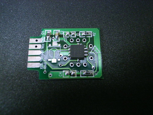
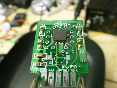
First job was a simple one. I have a bunch of Memsic MXC6202xJ two-axis accelerometers in a tiny LCC8 package, and a simple evaluation printed circuit board. The board had enough solder on the pads so I didn’t have to add any paste or anything.
I lined up the chip on the pads of the PCB and turned up the heat to around 350 degrees and waited..
In short order, the solder greyed, went molten and the chip took hold. I gave it a light tap with a tweezer and it fell right in place. Lowered the heat and the solder set and that was that. Terribly easy!
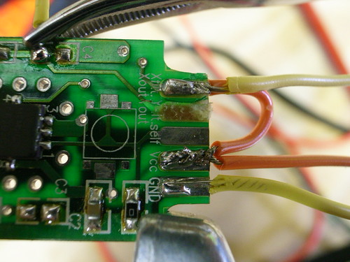
I had to solder a few wires to the edge connectors on the PCB to make set it up for some prototyping. I guess I put too much heat on one of the pads — it was tricky to get the wire lead to hold to the edge connector pad, so I used a hemostat. I guess it torqued a bit and the pad went ahead and lifted off of the PCB, damnit.
Fortunately, the other side of that particular trace went to a pad for an optional capacitor, so I could solder to that.
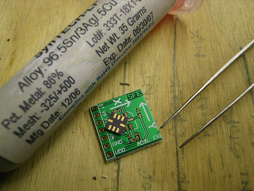
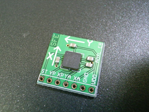
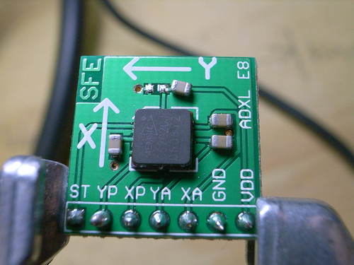
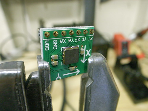
Here’s another quick surface-mount part I tossed together. It’s an improvised break-out board for mucking with the same Memsic MXC6202 dual-axis accelerometer as above. That board above — sold as an evaluation platform directly from Memsic — is pretty lousy if you ask me. $10.95, it doesn’t match up with its schematic, pads came off, it had an edge connector (for what?) when headers or a simple solder tail seems more appropriate for evaluation. Anyway..I had some boards for evaluating another chip with the same LCC8 footprint, so I just improvised.
Here I applied my own solder paste (the previous board had blobs of solder already on the board), and used this no-lead, no-clean paste manufactured by SynTech that supposedly doesn’t require refrigeration (I refrigerate it anyway.) I got it from Stencils Unlimited. The next-day shipping cost as much as the product itself..and they make you ship next day so the goo doesn’t sit in a baking hot UPS facility and get ruined.
The solder-paste they sent me came with a plunger for the applicator and a couple of simple, conical applicator tips, but I already had a selection of applicators with a couple different sized metal tips. I guess you could snip the plastic applicator tips to the size you wanted and things would be just fine. I chose to use a narrow gauge metal tip this time, from the small kit of tips I got from Zeph, the applicator tip king.
Here’s my little board all laid out with too much solder paste applied. I’d end up doing this one over — it made me nervous. I tapped the part while it was in the skillet and it slid over — I could see that the paste had smeared all over the place and was likely going to short pins out. I just removed the part, wiped the board clean and re-applied a much smaller quantity of paste. It would’ve been a good idea to let the paste get a little warmer so it was more viscous before I started working. This stuff was running a bit thick, which made it harder to apply very small dots of paste.
Here we are in the skillet — the solder has pretty much reflowed. I’d later find out that the two capacitors off of pins 6 and 7 were (a) the wrong part and, (b) supposed to be pull-up resistors and, (c) unnecessary because I had my own pull-up resistors on the breadboard. The upside? This was good practice doing some rework — I had to remove the parts to make the board work. I used the hot air station I got from Spark Fun. It’s relatively slow going to blow air and melt the paste, but it definitely works. Patience is required. I had to resist the urge to just crank the heat way up and blow like the Santa Ana’s — this hot air station will quickly melt the PCB. It’s super hot. I’m completely paranoid about this hot air station — it’s got no safety or auto-off or anything. I mean..I unplug the whole thing when I leave the laboratory. Turning the power switch to off just somehow doesn’t seem to be enough.
I also found that the bypass capacitor here was hiding a short, probably because I put on too much solder paste and it likely smeared under the there. I removed the part, wiped the area clean, and then reflowed it, this time using hot air directly on the device, as opposed to throwing the whole thing in the skillet which just would’ve heated everything up and that’s no good.
That’s that.
Here is my growing collection of links related to technique, supplies, etc. for backyard surface-mount technology work.
#include
#include


// TWI (I2C) sketch to communicate with the Memsic MXC6202J accelerometer
// Using the Wire library (created by Nicholas Zambetti)
// http://wiring.org.co/reference/libraries/Wire/index.html
// On the Arduino board, Analog In 4 is SDA, Analog In 5 is SCL
// These correspond to pin 27 (PC4/ADC4/SDA) and pin 28 (PC5/ADC5/SCL) on the Atmega8
// The Wire class handles the TWI transactions, abstracting the nitty-gritty to make
// prototyping easy.

void setup()
{
  Serial.begin(9600);
  Serial.println("Naah??");
  Wire.begin(); // join i2c bus (address optional for master)
}

void loop()
{

  byte x_val_l, x_val_h, y_val_l, y_val_h;
  int x_val, y_val;
  //byte in_byte;
  // transmit to device with address 0x1D
  // according to the LIS3L* datasheet, the i2c address of is fixed
  // at the factory at 0011101b (0x1D)

  Wire.beginTransmission(0x10);
  Wire.send(0x00); // CTRL_REG1 (20h)
  Wire.send(0xF0);
  Wire.endTransmission();

  delay(100);

  Wire.beginTransmission(0x10);
  Wire.send(0x00); // CTRL_REG1 (20h)
  //Wire.send(0x00); // address to start reads
  Wire.endTransmission();

  /*
  Wire.beginTransmission(0x22);
  Wire.send(0x00); // CTRL_REG1 (20h)
  Wire.endTransmission();

  Wire.beginTransmission(0x24);
  Wire.send(0x00); // CTRL_REG1 (20h)
  Wire.endTransmission();
  */

  Wire.requestFrom(0x10,5);
  while(Wire.available()) {
    Serial.print(Wire.receive(), HEX); // drop the internal register on the floor..
  }
  Serial.println("****");

  if(Wire.available()) {
    x_val_h = Wire.receive();
  }
  if(Wire.available()) {
    x_val_l = Wire.receive();
  }
  if(Wire.available()) {
    y_val_h = Wire.receive();
  }
  if(Wire.available()) {
    y_val_l = Wire.receive();
  }
    x_val = (x_val_h << 8); x_val |= x_val_l;
    y_val = (y_val_h << 8); y_val |= y_val_l;
  Serial.print(x_val_h, HEX); Serial.print(" "); Serial.print(x_val_l, HEX); Serial.print("n");
  Serial.print(y_val_h, HEX); Serial.print(" "); Serial.print(y_val_l, HEX); Serial.print("n");
 Serial.println("===");

Wire.endTransmission();

  delay(200);
}


The link to the arduino code is broken, could you send me the code ? I’am trying to work with the same device, but i can’t get it working …
Thanks