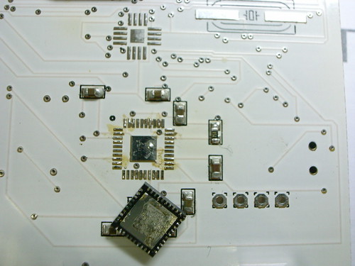
Wow, what a bit of a learning experience this was. That chip is an Invernsense IDG300 gyroscope. $35 a pop. And its one of these “QFN” (quad, flat, no leads) style packages which basically makes it a pain to work with. I thought I could use this technique of dabbing a bit of solder on each of the pads on the printed circuit board and then put a bit of heat to the board with hot air or an iron on each pad. It “took” but there was no electrical continuity. What I think happened is that the big center ground pad took hold, but the other leads didn’t. It seems like it should have. The alignment was good after eyeballing it. Anyway, it didn’t.
So, after taking the thing on and off a few times because of some shorts I found across a capacitor and crap, I decided to have a go with a bit of solder paste. That was something I was trying to stay away from because the paste is messy and difficult to apply to such small leads (.25mm or .01 inch). This is what you really need a stencil for, I guess.

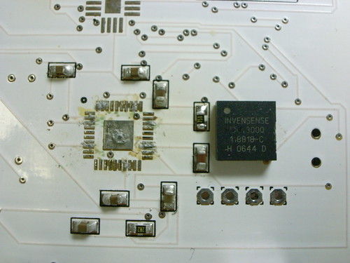
I dabbed a bit, messed it up, dabbed some more, cleaned up, etc. I basically just put paste on the leads that are actually connected to something. There are lots of non-connects, evidently for factory calibration of the device. With the solder paste on, I placed the chip, messed with it for a bit to try to get it aligned good, which is a bit nerve wracking because I’m trying to avoid accidentally spreading the solder paste around and everything. Finally, it looks good and I put some hot-air to the area. It sort of works when I check the electricals, so I try again, finally getting something. One of the devices seems a bit out of kilter — the rates on one axis when its static seems off, but maybe that can be compensated. We’ll see.
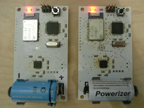
Power, but who knows how well it works? The MCUs are fine, power is fine, the Bluetooth radios there are fine. Haven’t had the nerve to check the gyros though..Those things came on and off so many times, I toasted the board a bit.
Technorati Tags: Near Future Laboratory