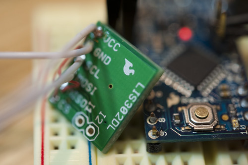
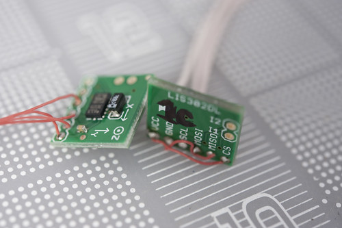
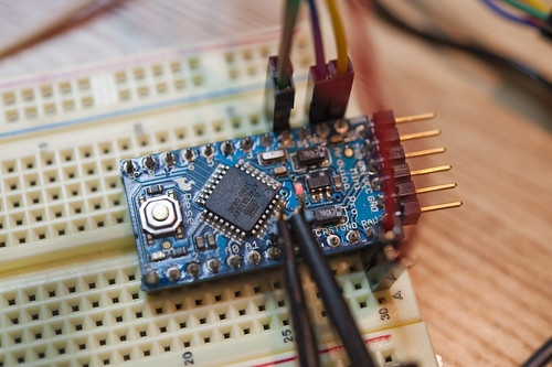
Ooooh. Those code jockeys in the Laboratory have been mucking about in the ol’ locker room, giving each other rat-tails, chucking firecrackers in the halls and having a good horsin’ around. Smoking cigarettes and drinking cheap booze. Everything. Stink bombs in the girl’s room. Whatever. It’s a regular Lord of the Flies fest on the electronics wing of the Near Future Laboratory. And, look what we found! Some pole dancin’ hardware porn! Step right up! Don’t crowd..
In reverent honor of my friends and chums who are holding forth with Sketching in Hardware 09 in London and for the solemn sadness I have for not being able to participate this year, I hereby drop some code and hardware science up on this piece of blog with a dozen or so lines of Arduinoness meant to articulate and instrumentalize the wonderful ST Micro LIS302DL 3 axis accelerometer, delivered here via the Sparkfun breakout board. Without further ado, but with plenty of firmware nakedness, here’s the sketch..*slug* this one’s for you, Sketchers..*sob*
#include

// TWI (I2C) sketch to communicate with the LIS302DL accelerometer
// Using the Wire library (created by Nicholas Zambetti)
// http://wiring.org.co/reference/libraries/Wire/index.html
// On the Arduino board, Analog In 4 is SDA, Analog In 5 is SCL
// These correspond to pin 27 (PC4/ADC4/SDA) and pin 28 (PC5/ADC5/SCL) on the Atmega8 and Atmega168
// The Wire class handles the TWI transactions, abstracting the nitty-gritty to make
// prototyping easy.

// We've got two accelerometers connected. You configure the address of each one
// by some wiring
int address_1 = 0x1C; // SDO on the LIS302DL connected to GND makes it at I2C address 0x1C
int address_2 = 0x1D; // SDO/MISO on the LIS302DL connected to VCC makes it at I2C address 0x1D
void setup()
{
  // we'll use the serial port to spit out our data
  Serial.begin(9600);

  byte tmp;

  Wire.begin(); // join i2c bus (address optional for master)


  // Read from the "WHO_AM_I" register of the LIS302DL and see if it is at
  // the expected address.
  // If it is not, spit out a useful message on the serial port. We'll get
  // erroneous data from querying this address, though.
  Wire.beginTransmission(address_1);
  Wire.send(0x0F);
  Wire.endTransmission();
  Wire.requestFrom(address_1,1);
  while(Wire.available()) {
   tmp = Wire.receive();
   if(tmp != 0x3B) {
     Serial.print("Problem! Can't find device at address "); Serial.println(address_1, HEX);
     delay(1000);
   } else {
  // configure the device's CTRL_REG1 register to initialize it
  Wire.beginTransmission(address_1);
  Wire.send(0x20); // CTRL_REG1 (20h)
  Wire.send(B01000111); // Nominal data rate, Device in active mode, +/- 2g scale, self-tests disabled, all axis's enabled
  Wire.endTransmission();
   }
  }


  // Read from the "WHO_AM_I" register of the second LIS302DL and see if it is at
  // the expected address.
  // If it is not, spit out a useful message on the serial port. We'll get
  // erroneous data from querying this address, though.
  Wire.beginTransmission(address_2);
  Wire.send(0x0F);
  Wire.endTransmission();
  Wire.requestFrom(address_2,1);
  while(Wire.available()) {
   tmp = Wire.receive();
   if(tmp != 0x3B) {
     Serial.print("Problem! Can't find device at address "); Serial.println(address_2, HEX);
     delay(1000);
   } else {

  // configure the device's CTRL_REG1 register to initialize it
  Wire.beginTransmission(address_2);
  Wire.send(0x20); // CTRL_REG1 (20h)
  Wire.send(B01000111); // Nominal data rate, Device in active mode, +/- 2g scale, self-tests disabled, all axis's enabled
  Wire.endTransmission();
   }
  }
}

void loop()
{
  Serial.print("1:"); read_acceleration(address_1);
  Serial.print("2:"); read_acceleration(address_2);
}

void read_acceleration(int address) {
  byte z_val_l, z_val_h, x_val_l, x_val_h, y_val_l, y_val_h;
  int z_val, x_val, y_val;
  Wire.beginTransmission(address);
 // Now do a transfer reading one byte from the LIS302DL
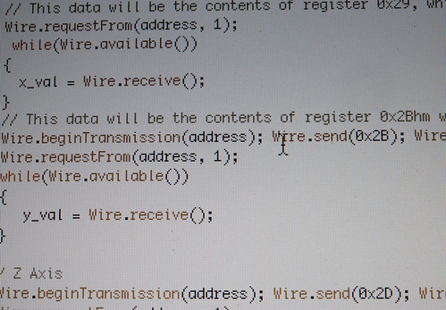
 // This data will be the contents of register 0x29, which is OUT_X
  Wire.send(0x29);
  Wire.endTransmission();
 Wire.requestFrom(address, 1);
  while(Wire.available())
 {
   x_val = Wire.receive();
 }
 // This data will be the contents of register 0x2B which is OUT_Y
 Wire.beginTransmission(address);
 Wire.send(0x2B);
 Wire.endTransmission();
 Wire.requestFrom(address, 1);
 while(Wire.available())
 {
    y_val = Wire.receive();
 }

 // This data will be the contents of register 0x2D, which is OUT_Z
 Wire.beginTransmission(address);
 Wire.send(0x2D);
 Wire.endTransmission();
 Wire.requestFrom(address, 1);
 while(Wire.available())
 {
    z_val = Wire.receive();
 }

 // I want values that run from {-X to 0} and {0 to +X}, so a little bit math goes on here...
 if(bit_is_set(x_val, 7)) {
   x_val &= B01111111;
   x_val = -1*x_val + 128;
   x_val *= -1;
 }

if(bit_is_set(y_val, 7)) {
   y_val &= B01111111;
   y_val = 128 - y_val;
   y_val *= -1;
 }

 if(bit_is_set(z_val, 7)) {
   z_val &= B01111111;
   z_val = 128 - z_val;
   z_val *= -1;
 }

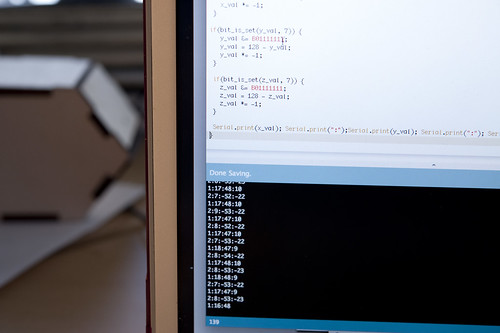
 Serial.print(x_val); Serial.print(":");Serial.print(y_val); Serial.print(":"); Serial.println(z_val);
}
What’s going on here? Well, straightforward silliness and hardware gafflin’. Two accelerometers on the I2C bus just cause. It looks like this is as many as you can have on there, unless you do some shenanigans or create a second bus with some cleverness.
The hardware spec on the device (Which. You. Should. Read.) explains that, if we’re going to talk to these things using the I2C bus we need to wire CS to the high end of the logic rail, so VCC. This tells the device that we’ll be using I2C protocol. Then we need to address the device. If we connect the MISO (master in, slave out) pin to GND, then the address will be 0x1C. If we connect the MISO pin to VCC, then the address will be 0x1D. So, MISO, in the I2C configuration, controls the least significant bit of the address. This way, without further mucking about, we can have two accelerometers on the bus, which is probably one more than most situations demand, but just in case.
If I were to connect more than two, I would probably go ahead and use the three-wire protocol and have one microcontroller pin per accelerometer dedicated for chip-select (CS). Fortunately, this device supports three-wire protocols, or the SPI protocol.
The Arduino code example above does some simple preambling — initializing the two devices after making sure they are there. Then it just loops forever, reading accelerometer data from each of the three axes of each one, doing a little simple bitwise arithmetic to make the data from a negative value for negative g (upside down in most situations) to positive g (right side up, in most situations). The initialization stage sets the accelerometer range — that is, the max/min values it will read — to +/- 2g. (The device will support +/- 8g according to the specifications.)
There are some cool additional features that I don’t play with, including some interrupts that can be triggered if the device falls suddenly, or if it is “clicked/tapped” or “double-clicked/double-tapped”, which is kinda cool, I guess. If you can come up with a non-gratuitous scenario. Which is probably harder than it sounds. But, even in your gratuitous-I-double-click-my-glass-of-Porto-to-signal-the-waiter-I-need-more-Porto the device will save you the hassle of trying to do this sort of interaction semantics in firmware and get you back to finishing what you were doing in the first place.
Why do I blog this? Notes on the integration of hardware to firmware to ideas. This time with a “new” accelerometer that has some pretty neat features. After this, we’ll be going to paper-pulp and line drawings for a bit folks.
