LIS302DL. A 3 Axis Accelerometer

Tuesday July 14, 13.12.21

Ooooh. Those code jockeys in the Laboratory have been mucking about in the ol’ locker room, giving each other rat-tails, chucking firecrackers in the halls and having a good horsin’ around. Smoking cigarettes and drinking cheap booze. Everything. Stink bombs in the girl’s room. Whatever. It’s a regular Lord of the Flies fest on the electronics wing of the Near Future Laboratory. And, look what we found! Some pole dancin’ hardware porn! Step right up! Don’t crowd..

Wednesday July 15, 13.04.33

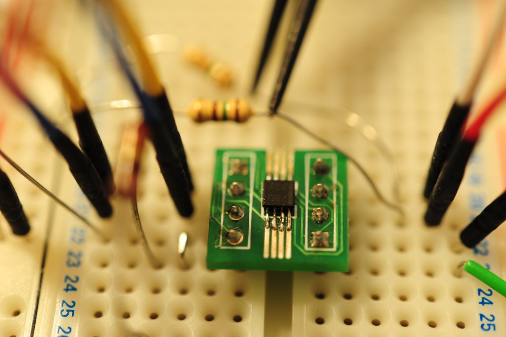
In reverent honor of my friends and chums who are holding forth with Sketching in Hardware 09 in London and for the solemn sadness I have for not being able to participate this year, I hereby drop some code and hardware science up on this piece of blog with a dozen or so lines of Arduinoness meant to articulate and instrumentalize the wonderful ST Micro LIS302DL 3 axis accelerometer, delivered here via the Sparkfun breakout board. Without further ado, but with plenty of firmware nakedness, here’s the sketch..*slug* this one’s for you, Sketchers..*sob*

#include

// TWI (I2C) sketch to communicate with the LIS302DL accelerometer
// Using the Wire library (created by Nicholas Zambetti)
// http://wiring.org.co/reference/libraries/Wire/index.html
// On the Arduino board, Analog In 4 is SDA, Analog In 5 is SCL
// These correspond to pin 27 (PC4/ADC4/SDA) and pin 28 (PC5/ADC5/SCL) on the Atmega8 and Atmega168
// The Wire class handles the TWI transactions, abstracting the nitty-gritty to make
// prototyping easy.

// We've got two accelerometers connected. You configure the address of each one
// by some wiring
int address_1 = 0x1C; // SDO on the LIS302DL connected to GND makes it at I2C address 0x1C
int address_2 = 0x1D; // SDO/MISO on the LIS302DL connected to VCC makes it at I2C address 0x1D
void setup()
{
  // we'll use the serial port to spit out our data
  Serial.begin(9600);

  byte tmp;

  Wire.begin(); // join i2c bus (address optional for master)


  // Read from the "WHO_AM_I" register of the LIS302DL and see if it is at
  // the expected address.
  // If it is not, spit out a useful message on the serial port. We'll get
  // erroneous data from querying this address, though.
  Wire.beginTransmission(address_1);
  Wire.send(0x0F);
  Wire.endTransmission();
  Wire.requestFrom(address_1,1);
  while(Wire.available()) {
   tmp = Wire.receive();
   if(tmp != 0x3B) {
     Serial.print("Problem! Can't find device at address "); Serial.println(address_1, HEX);
     delay(1000);
   } else {
  // configure the device's CTRL_REG1 register to initialize it
  Wire.beginTransmission(address_1);
  Wire.send(0x20); // CTRL_REG1 (20h)
  Wire.send(B01000111); // Nominal data rate, Device in active mode, +/- 2g scale, self-tests disabled, all axis's enabled
  Wire.endTransmission();
   }
  }


  // Read from the "WHO_AM_I" register of the second LIS302DL and see if it is at
  // the expected address.
  // If it is not, spit out a useful message on the serial port. We'll get
  // erroneous data from querying this address, though.
  Wire.beginTransmission(address_2);
  Wire.send(0x0F);
  Wire.endTransmission();
  Wire.requestFrom(address_2,1);
  while(Wire.available()) {
   tmp = Wire.receive();
   if(tmp != 0x3B) {
     Serial.print("Problem! Can't find device at address "); Serial.println(address_2, HEX);
     delay(1000);
   } else {

  // configure the device's CTRL_REG1 register to initialize it
  Wire.beginTransmission(address_2);
  Wire.send(0x20); // CTRL_REG1 (20h)
  Wire.send(B01000111); // Nominal data rate, Device in active mode, +/- 2g scale, self-tests disabled, all axis's enabled
  Wire.endTransmission();
   }
  }
}

void loop()
{
  Serial.print("1:"); read_acceleration(address_1);
  Serial.print("2:"); read_acceleration(address_2);
}

void read_acceleration(int address) {
  byte z_val_l, z_val_h, x_val_l, x_val_h, y_val_l, y_val_h;
  int z_val, x_val, y_val;
  Wire.beginTransmission(address);
 // Now do a transfer reading one byte from the LIS302DL
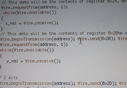
 // This data will be the contents of register 0x29, which is OUT_X
  Wire.send(0x29);
  Wire.endTransmission();
 Wire.requestFrom(address, 1);
  while(Wire.available())
 {
   x_val = Wire.receive();
 }
 // This data will be the contents of register 0x2B which is OUT_Y
 Wire.beginTransmission(address);
 Wire.send(0x2B);
 Wire.endTransmission();
 Wire.requestFrom(address, 1);
 while(Wire.available())
 {
    y_val = Wire.receive();
 }

 // This data will be the contents of register 0x2D, which is OUT_Z
 Wire.beginTransmission(address);
 Wire.send(0x2D);
 Wire.endTransmission();
 Wire.requestFrom(address, 1);
 while(Wire.available())
 {
    z_val = Wire.receive();
 }

 // I want values that run from {-X to 0} and {0 to +X}, so a little bit math goes on here...
 if(bit_is_set(x_val, 7)) {
   x_val &= B01111111;
   x_val = -1*x_val + 128;
   x_val *= -1;
 }

if(bit_is_set(y_val, 7)) {
   y_val &= B01111111;
   y_val = 128 - y_val;
   y_val *= -1;
 }

 if(bit_is_set(z_val, 7)) {
   z_val &= B01111111;
   z_val = 128 - z_val;
   z_val *= -1;
 }

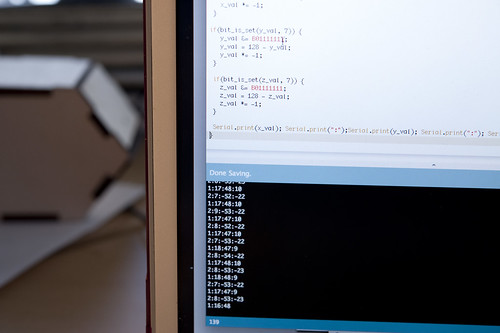
 Serial.print(x_val); Serial.print(":");Serial.print(y_val); Serial.print(":"); Serial.println(z_val);
}

Tuesday July 14, 13.09.59

Wednesday July 15, 14.37.44

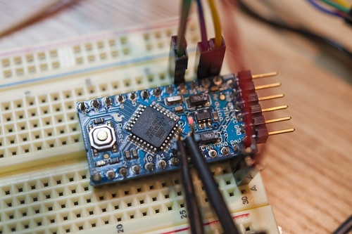
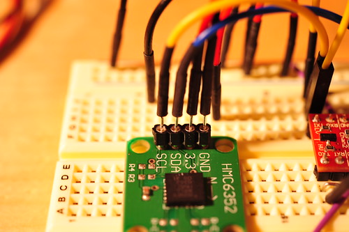
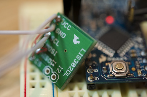
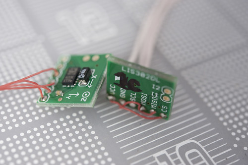
What’s going on here? Well, straightforward silliness and hardware gafflin’. Two accelerometers on the I2C bus just cause. It looks like this is as many as you can have on there, unless you do some shenanigans or create a second bus with some cleverness.

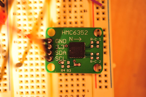
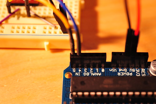
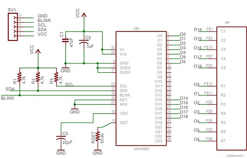
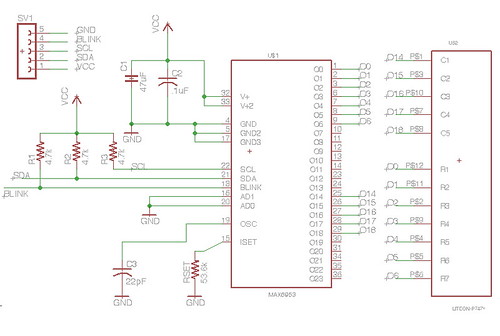
The hardware spec on the device (Which. You. Should. Read.) explains that, if we’re going to talk to these things using the I2C bus we need to wire CS to the high end of the logic rail, so VCC. This tells the device that we’ll be using I2C protocol. Then we need to address the device. If we connect the MISO (master in, slave out) pin to GND, then the address will be 0x1C. If we connect the MISO pin to VCC, then the address will be 0x1D. So, MISO, in the I2C configuration, controls the least significant bit of the address. This way, without further mucking about, we can have two accelerometers on the bus, which is probably one more than most situations demand, but just in case.

If I were to connect more than two, I would probably go ahead and use the three-wire protocol and have one microcontroller pin per accelerometer dedicated for chip-select (CS). Fortunately, this device supports three-wire protocols, or the SPI protocol.

Tuesday July 14, 13.17.11

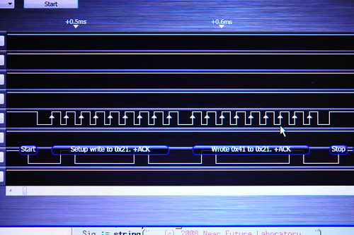
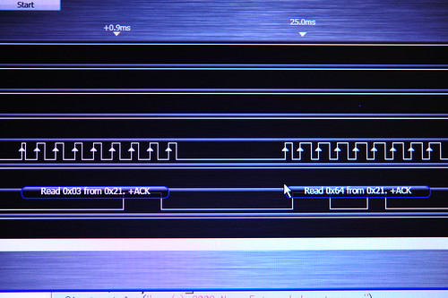
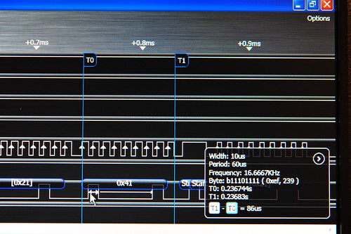
The Arduino code example above does some simple preambling — initializing the two devices after making sure they are there. Then it just loops forever, reading accelerometer data from each of the three axes of each one, doing a little simple bitwise arithmetic to make the data from a negative value for negative g (upside down in most situations) to positive g (right side up, in most situations). The initialization stage sets the accelerometer range — that is, the max/min values it will read — to +/- 2g. (The device will support +/- 8g according to the specifications.)

There are some cool additional features that I don’t play with, including some interrupts that can be triggered if the device falls suddenly, or if it is “clicked/tapped” or “double-clicked/double-tapped”, which is kinda cool, I guess. If you can come up with a non-gratuitous scenario. Which is probably harder than it sounds. But, even in your gratuitous-I-double-click-my-glass-of-Porto-to-signal-the-waiter-I-need-more-Porto the device will save you the hassle of trying to do this sort of interaction semantics in firmware and get you back to finishing what you were doing in the first place.

Why do I blog this? Notes on the integration of hardware to firmware to ideas. This time with a “new” accelerometer that has some pretty neat features. After this, we’ll be going to paper-pulp and line drawings for a bit folks.

A New Logic Analyzer and the HMC6352 I2C Compass

25092008_023841

25092008_024008

Two things that’ve been sitting on my bench for a good spell — this HMC6352 magnetic compass with an I2C interface, and the Saleae “Logic” logic analyzer. I figured I could combine the two together, showing how I used the Logic to check out the operation of the HMC6352.

First, the HMC6352 is a pretty easy to use magnetic compass with 0.5 degree accuracy. It’s all wrapped up nicely with a pretty normal I2C interface to a bunch of registers on the device, and command-driven queries for reading the compass heading.

The Saleae “Logic” logic analyzer is pretty sweet for debugging I2C as I’ve mentioned in the past. This one is nice and compact, with a reasonable bunch of logic lines for doing simple analysis. I played with this one for a number of projects over the last few months — mostly I2C projects, which is where most of my interface work is these days. But, the “Logic” will also work with a bunch of stock “analyzers” for RS232 and SPI as well, making it pretty versatile for many situations.

The analyzer is a pretty compact package — 1.6″ square and only .36″ high. So, basically miniature for a logic analyzer. It comes with a 9 conductor umbilical along with E-Z-Hook XKM probes that you can use or not, depending on how you’re hooking up to things.

25092008_024813

25092008_025316

The Logic has a pretty easy-to-use bit of front-end software to handle all the set-up and UI work for the teeny-tiny hardware. It’s a UI that is unlike what you might expect from a bit of Windows-based software. It’s very gooey, using some subtle screen effects and UI elements that, for this OSX guy, are not what I think of when I think of XP. Which is good. It makes using the UI not feel like I’m being forced to drink a Rusty Nail or something for breakfast.

The analyzer samples much quicker than I normally have need for and does so without any problems. I’m usually down in the low range — .2 MHz and 1 M samples is usually plenty for what I’m doing. But, if you need a wider range of samples or a higher sample rate, the analyzer will go all the way up to 24 MHz. Those 9 conductors are 8 data lines plus one ground, so you can analyzer an 8-bit wide bus if you wanted at 24 MHz.

So, I put the Saleae Logic on the HMC6352 circuit to give it a shot. First, the HMC6352 set-up.

Although the HMC6352 has a wide voltage range, I was playing around with a level shifter circuit that was already hooked up to an Arduino on the bench, so I went ahead and just kept that circuit as is. So, the basic set-up is my Arduino I2C lines (SDA and SCL) going through a bi-directional level shifter shifts 3.3V 5V, and then to the HMC6352 SDA and SCL lines. I use yellow wire for SCL and blue wire for SDA.

25092008_024251

25092008_024344

I ended up using the Saleae Logic to dig a bit deeper into the communication between my microcontroller (an Atmega168 sitting on an Arduino) and the HMC6352 as a way to test out the logic analyzer.

First I wanted to just probe the I2C communication. The basic transaction my Arduino code was doing was to send an “A” to the HMC6352. According to the specification sheet, writing an “A” to the device causes it to return two bytes of data — the high-order and low-order bytes of a 16 bit value indicating the compass’ heading. Easy enough. Here’s the Arduino doing just that. First, it sets up the write to the I2C device at address 0x21. Then it writes an “A” which, in the ASCII table, is the value 0x41. (N.B. The spec sheet says the HMC6352 is at address 0x42 but — and don’t ask me why — sometimes the address specified has to be right-shifted one bit in order to “take”. I mean I sort of know why, but I don’t know why this is the case sometimes — a r/w bit thing or something. Too much to bother with, but a good way to make good use of a logic analyzer when you’re stuck wondering why your device doesn’t seem to be listening to you. I learned this the long way and only had a fancy DSO to try and debug it.)

25092008_025019

25092008_025136

25092008_025615

There it is in the top picture. A simple write to the device at address 0x21 with all the ACKs, meaning whatever is out there, heard us and is acknowledging receipt of the write. And, it looks like we get two bytes of data back — a 0x03 and a 0x64. The first byte will be the high-order byte and the second byte is the low-order byte. 0x0364 is 868, which we normalize by dividing by 10, to get 86.8 degrees. Done. I’m pretty sure that’s that. Finally, the measurement features are pretty cool — useful for confirming clock speeds or verifying a bit train. There’s a good use of a simple, pretty inexpensive ($150) logic analyzer that’ll certainly save you $150 worth of your time many times over. Plus, the small size and convenience of USB make it easy enough to fit on your bench and store away or travel around with when it’s not in use. My only quibble is that it’s only for Windows, but that’s a minor one. I don’t really play too hard in the OS religious wars. I run whatever makes my life easier at whatever moment. So, a $200-ish Windows chassis in the laboratory that just runs a few apps like some CAD software and things like my Propeller coding environment, .NET development, software for test equipment like this and AVR Studio 4 — it just helps me get things done rather than being adamantine about which OS religion I’ll adhere to and, then, not getting anything done except spending time porting things from one OS to another or complaining about how much a Windows license costs or whatever.

Wow. Okay. Off my high horse. Check this logic analyzer out. I can recommend it after using it for a few months.

#include

// http://wiring.org.co/reference/libraries/Wire/index.html
// On the Arduino board, Analog In 4 is SDA, Analog In 5 is SCL
// The Wire class handles the TWI transactions, abstracting the nitty-gritty to make
// prototyping easy.
// This sketch has a HMC6352 attached to the I2C bus, through a bi-directional
// level-shifter circuit.
int address = 0x42 >> 1;
 int reading;
void setup()
{

  Serial.begin(9600);

  CLKPR = (1<<clkpce);
  CLKPR = 0;

  // initialize the TWI / I2C Bus
  Wire.begin(); // join i2c bus (address optional for master)

}

void loop() {

  Wire.beginTransmission(address);
  Wire.send('A');
  Wire.endTransmission();
  //delay(10);
  Wire.requestFrom(address, 2);

   if(2 <= Wire.available())    // if two bytes were received
  {
    reading = Wire.receive();  // receive high byte (overwrites previous reading)
    reading = reading << 8;    // shift high byte to be high 8 bits
    reading += Wire.receive(); // receive low byte as lower 8 bits
    reading /= 10;
    Serial.println(reading);   // print the reading
  }

//  delay(50);
}

Continue reading A New Logic Analyzer and the HMC6352 I2C Compass

PCA9306 Level Shifter

Persistent nagging problem — shifting logic levels between devices that are fabbed with different technologies so their voltages end up being different. Digital circuits “trigger” based on voltage levels — a logic 1 or high signal is relative to the electrical specifications of the device and the fabrication process of the silicon. (A techie diagram is available here.) It’s not a new problem, but one I seem to be coming across more and more as I use the Arduino to do quick sketches of project ideas, or to stand-in for a more embedded solution that might use another of the Atmel 8-bit devices later on when the design and details are more refined.

I’ve tried a bunch of things, including the kind of canonical reference circuit from Philips that uses the BSN20 MOSFET. Sparkfun has a neat little breakout board using a MOSFET, the BSS138. Same principle, built out for you by the fine folk at Sparkfun.

While poking around some more what cause of this PSX project where I have an Arduino trying to talk to a Parallax Propeller, I found reference to a single-chip solution from TI that’s called a PCA9306, which is that small guy up in the photos above. (Just a hair smaller than an 8-pin SSOP package, which means that it was too small to fit on this SSOP break-out — the pins don’t reach the copper, so I had Igor do some hand work to get that to take hold.
Continue reading PCA9306 Level Shifter

Propeller and Arduino

Not the most exciting thing, but an interesting challenge here. I’m trying to get a Parallax Propeller chip to behave nicely as an TWI/I2C slave with the idea that I’d like to create a pretty much black-box interface that’ll allow a TWI/I2C master to control it for stuff. Ultimately I’d like to use the Propeller in the PSX project. It’ll sit in between a Playstation 2 and a normal Playstation controller, and be available as a TWI/I2C slave, so that another device, that doesn’t really care to figure out how to talk to a Playstation 2 or its controllers can make the PSX box with the Propeller in it emulate, for the Playstation, certain button presses, etc. Or, it could “read” over TWI/I2C from the PSX box and find out what the real controller is doing. Or, it could just read or write from a special TWI register address to make the PSX box (with the Propeller in it) just do a “pass-thru” so that the signals just go straight through as if there were nothing in between.

That’s the theory. In practice, setting up this test jig took more time that I would’ve thought.
Continue reading Propeller and Arduino

The Ersatz Cylon Detector: A Hardware Sketch To Illuminate The Inner Workings of the MAX6953 Integrated Circuit

Cylon Detector In Operation

An on-going project that requires the display of alphabetic and numeric characters using a 5×7 LED matrix turned me towards a chip by Maxim IC — the MAX6953. The chip, while expensive (~$8), has lots of built-in features that mitigate the damage to my purse, trading such in kind for time-saved. It will directly drive up to 4 5×7 LED matrices with direct control from a microcontroller over a two-wire interface (TWI/I2C), can manage varying intensities (16 or 32 degree scales), has a built-in Arial-like font set with a reasonably full-range of characters, diacritics and symbols, and allows me to create 24 characters of my own design.

Here’s my Eagle PCB library of the MAX6951 and MAX6953; feel free to use it.

SlowMessenger_Max6953_Breakout

SlowMessenger_Max6953_Breakout_Board

My first attempt at mucking with the chip used the DIP version, which is ginormous and requires such patience and diligence with wiring the thing up — all those lines going to the pins of the LED matrix — that I pretty much gave up after it didn’t work the first time. I decided that I’d just go ahead and design a PCB for the thing and continue to hone my skills with Eagle, while also learning how to work with the MAX6953.

Some Samples

I sent a design off, it came back, I stared at it for a few minutes, looked for the MAX6953’s in my bin of samples and realized I didn’t have any. I managed to coax a bunch from Maxim’s sample guy, which is great. (Thanks whoever you are, wherever you are.) A couple of weeks later, when my plate was relatively clear, I assembled one of the boards, using a yellowish/orange 5×7 matrix LED I purchased from Digikey and manufactured by LiteOn. I wanted small, but the closest I got to small was 0.7″, which still seems big to me. (The story of it’s assembly and problems therein is instructive if you’re curious about surface-mount PCB work..and the problems therein.)

I powered the thing up and, naturally enough, it didn’t illuminate at all. I poked through the spec sheet and figured out that there’s a whole start-up ritual you’ll want to go through, such as the test mode and negating the shutdown bit, which defaults to “shutdown enabled.” After an hour or so of puzzling, I managed to get it displaying characters while hooked up to my usual Arduino test harness thing.

Lower "T"

While I was assembling the board, I realized I wasn’t sure what the proper orientation of the LED device should be. I looked for markings to indicate pin 1 and found nothing definitive. I looked at the product data sheet and they had an arrow pointing at pin 1 but nothing that clearly told me how to determine which of the pins was the first. Now, the holes I put in for the LED device in Eagle were a bit snug — too snug, really. It required a bit of jiggering to get the LED device to fit. (I went back and made the holes slightly bigger in the design.) But, I realized this could be an advantage given my current pin alignment peril — the snugness would allow the LED device’s pins to make contact with the through-holes’ platings! In other words, I could fit the device one way and not solder the pins to see if I had the thing right-way-around.

Evil Rabbit Character

Well, that worked. A consequence of it working was that some of the columns and rows didn’t illuminate quite consistently — they’d flicker and such — and a mysterious character appeared — an evil rabbit was the first thing I saw.

I ran through a few code gyrations and got characters to show, right-way-around, so I went ahead and soldered the LED device permanently to the board, easy-peasy.

Thinking of a few possible ways to make this learning project fun to share for the show-and-tell session of the weekly luncheon I have with some friends, I decided that I’d make a combination Magic 8 Ball / Cylon Detector, the idea being that one could reasonably ask the Magic 8 Ball if one were a Cylon — I mean..why not? — which would be a lot easier than what Baltar was trying to construct, and wouldn’t require blood samples or anything. You could just ask yourself, in the privacy of your own home or a public restroom, and then choose whether or not you wanted to share your result.

So, I hooked it up to an accelerometer that detects the normative shaking motion one inflicts on the Magic 8 Ball..the evil rabbit then divines the response.

Anyway, it definitely works.

The Ersatz Cylon Detector is meant for entertainment purposes only. It does not purport to factually report whether or not individuals are Cylons, except for Don Milvio. (He’s definitely a weird hybrid Franco-Italian Cylon thing.) The results are for home amusement and cannot be used for discovery or detection of actual Cylons, their friends or family. The results cannot be used for legal purposes, nor as a sanction for physical violence. The Ersatz Cylon Detector and its results are not endorsed by the producers of Battlestar Galactica, The SciFi Channel, or its affiliates and their station managers.


Arduino Code

#include <Wire.h>
#include <math.h>

// http://wiring.org.co/reference/libraries/Wire/index.html
// On the Arduino board, Analog In 4 is SDA, Analog In 5 is SCL
// These correspond to pin 27 (PC4/ADC4/SDA) and pin 28 (PC5/ADC5/SCL) on the Atmega8
// The Wire class handles the TWI transactions, abstracting the nittygritty to make
// prototyping easy.
// This sketch has two TWI devices connected to it — a LIS3LV02DQ triaxis accelerometer
// and the MAX6953 5x7 matrix LED driver. The MAX6953 is at address 0x50, and the LIS3LV02DQ is
// at address 0x1D.

char mAnswer_1[19] = {‘S’,‘i’,‘g’,‘n’,‘s’,‘ ‘,‘p’,‘o’,‘i’,‘n’,‘t’,‘ ‘,‘t’,‘o’,‘ ‘,‘y’,‘e’,‘s’,0x00};
char mAnswer_2[4] = {‘Y’,‘e’,‘s’,0x00};
char mAnswer_3[12] = {‘M’,‘o’,‘s’,‘t’,‘ ‘,‘l’,‘i’,‘k’,‘e’,‘l’,‘y’,0x00};
char mAnswer_4[16] = {‘W’,‘i’,‘t’,‘h’,‘o’,‘u’,‘t’,‘ ‘,‘a’,‘ ‘,‘d’,‘o’,‘u’,‘b’,‘t’,0x00};
char mAnswer_5{16] = {‘Y’,‘e’,‘s’,‘,’,‘ ‘,‘d’,‘e’,‘f’,‘i’,‘n’,‘i’,‘t’,‘e’,‘l’,‘y’,0x00};
char mAnswer_6[17] = {‘A’,‘s’,‘ ‘,‘I’,‘ ‘,‘s’,‘e’,‘e’,‘ ‘,‘i’,‘t’,‘,’,‘ ‘,‘y’,‘e’,‘s’,0x00};
char mAnswer_7[19] = {‘Y’,‘o’,‘u’,‘ ‘,‘m’,‘a’,‘y’,‘ ‘,‘r’,‘e’,‘l’,‘y’,‘ ‘,‘o’,‘n’,‘ ‘,‘i’,‘t’,0x00};
char mAnswer_8[13] = {‘O’,‘u’,‘t’,‘l’,‘o’,‘o’,‘k’,‘ ‘,‘g’,‘o’,‘o’,‘d’,0x00};
char mAnswer_9[14] = {‘I’,‘t’,‘ ‘,‘i’,‘s’,‘ ‘,‘c’,‘e’,‘r’,‘t’,‘a’,‘i’,‘n’,0x00};
char mAnswer_10[19] = {‘I’,‘t’,‘ ‘,‘i’,‘s’,‘ ‘,‘d’,‘e’,‘c’,‘i’,‘d’,‘e’,‘d’,‘l’,‘y’,‘ ‘,‘s’,‘o’,0x00};
char mAnswer_11[22] = {‘R’,‘e’,‘p’,‘l’,‘y’,‘ ‘,‘h’,‘a’,‘z’,‘y’,‘,’,‘ ‘,‘t’,‘r’,‘y’,‘ ‘,‘a’,‘g’,‘a’,‘i’,‘n’,0x00};
char mAnswer_12[24] = {‘B’,‘e’,‘t’,‘t’,‘e’,‘r’,‘ ‘,‘n’,‘o’,‘t’,‘ ‘,‘t’,‘e’,‘l’,‘l’,‘ ‘,‘y’,‘o’,‘u’,‘ ‘,‘n’,‘o’,‘w’,0x00};
char mAnswer_13[16] = {‘A’,‘s’,‘k’,‘ ‘,‘a’,‘g’,‘a’,‘i’,‘n’,‘ ‘,‘l’,‘a’,‘t’,‘e’,‘r’,0x00};
char mAnswer_14[26] = {‘C’,‘o’,‘n’,‘c’,‘e’,‘n’,‘t’,‘r’,‘a’,‘t’,‘e’,‘ ‘,‘a’,‘n’,‘d’,‘ ‘,‘a’,‘s’,‘k’,‘ ‘,‘a’,‘g’,‘a’,‘i’,‘n’,0x00};
char mAnswer_15[19] = {‘C’,‘a’,‘n’,‘n’,‘o’,‘t’,‘ ‘,‘p’,‘r’,‘e’,‘d’,‘i’,‘c’,‘t’,‘ ‘,‘n’,‘o’,‘w’,0x00};
char mAnswer_16[18] = {‘M’,‘y’,‘ ‘,‘s’,‘o’,‘u’,‘r’,‘c’,‘e’,‘s’,‘ ‘,‘s’,‘a’,‘y’,‘ ‘,‘n’,‘o’,0x00};
char mAnswer_17[14] = {‘V’,‘e’,‘r’,‘y’,‘ ‘,‘d’,‘o’,‘u’,‘b’,‘t’,‘f’,‘u’,‘l’,0x00};
char mAnswer_18[20] = {‘O’,‘u’,‘t’,‘l’,‘o’,‘o’,‘k’,‘ ‘,‘n’,‘o’,‘t’,‘ ‘,‘s’,‘o’,‘ ‘,‘g’,‘o’,‘o’,‘d’,0x00};
char mAnswer_19[18] = {‘D’,‘o’,‘n’,,‘t’,‘ ‘,‘c’,‘o’,‘u’,‘n’,‘t’,‘ ‘,‘o’,‘n’,‘ ‘,‘i’,‘t’,0x00};

void setup()
{

Serial.begin(9600);

CLKPR = (1<<CLKPCE);
CLKPR = 0;

// initialize the LIS3LV02DQ
Wire.begin(); // join i2c bus (address optional for master)
Wire.beginTransmission(0x1D);
Wire.send(0x20); // CTRL_REG1 (20h)
Wire.send(0x87); // Device on, 40hz, normal mode, all axiss enabled
Wire.endTransmission();

// initialize the MAX6953
Wire.beginTransmission(0x50);
Wire.send(0x07); // Display Test
Wire.send(0x00); // Normal Operation
Wire.endTransmission();

Wire.beginTransmission(0x50);
Wire.send(0x01); // Intensity16
Wire.send(0x0F); // Full
Wire.endTransmission();

Wire.beginTransmission(0x50);
Wire.send(0x04); // configuration register
Wire.send(0x01); // disable shutdown mode
Wire.endTransmission();
initializeSpecialCharacters();
}

void loop() {
int z_val, x_val, y_val;
int sum_sq, sum_sq_2, diff, mShake, message;
int max_accel;
byte i;

message = 0;

setCharacter(0x00);
delay(random(500,1000));
setCharacter(0x01);
delay(random(500,1500));

x_val = getX();
y_val = getY();
z_val = getZ();

sum_sq = sqrt(pow(x_val, 2) + pow(y_val, 2) + pow(z_val, 2));

delay(100);
x_val = getX();
y_val = getY();
z_val = getZ();
mShake = 0;
sum_sq_2 = sqrt(pow(x_val, 2) + pow(y_val, 2) + pow(z_val, 2));
diff = abs(sum_sqsum_sq_2);
if(diff > 300) { mShake = 1; }
if(diff > 1000) { mShake = 2; }
if(diff > 1200) { mShake = 3; }

//Serial.print(diff); Serial.print(" "); Serial.print(max_accel); Serial.print(" "); Serial.println(mShake);

if(diff > max_accel) max_accel = diff;

//delay(500);

if(mShake > 0) {
message = random(0,18);
for(int i=0; i<3; i++) {
setCharacter(‘*’); delay(500); setCharacter(‘ ‘); delay(500);
}
} else {
message = 1;
}
switch(message) {
case 0:
i = 0;
while(mAnswer_1[i] != 0x00) {
setCharacter(mAnswer_1[i]); delay(800);
i++;
}
break;
case 1:
i = 0;
while(mAnswer_2[i] != 0x00) {
setCharacter(mAnswer_2[i]); delay(800);
i++;
}
case 2:
i = 0;
while(mAnswer_3[i] != 0x00) {
setCharacter(mAnswer_3[i]); delay(800);
i++;
}
break;
case 3:
i = 0;
while(mAnswer_4[i] != 0x00) {
setCharacter(mAnswer_4[i]); delay(800);
i++;
}
break;
case 4:
i = 0;
while(mAnswer_5[i] != 0x00) {
setCharacter(mAnswer_5[i]); delay(800);
i++;
}
break;
case 5:
i = 0;
while(mAnswer_5[i] != 0x00) {
setCharacter(mAnswer_5[i]); delay(800);
i++;
}
break;
case 6:
i = 0;
while(mAnswer_6[i] != 0x00) {
setCharacter(mAnswer_6[i]); delay(800);
i++;
}
break;
case 7:
i = 0;
while(mAnswer_7[i] != 0x00) {
setCharacter(mAnswer_7[i]); delay(800);
i++;
}
break;
case 8:
i = 0;
while(mAnswer_8[i] != 0x00) {
setCharacter(mAnswer_8[i]); delay(800);
i++;
}
break;
case 9:
i = 0;
while(mAnswer_9[i] != 0x00) {
setCharacter(mAnswer_9[i]); delay(800);
i++;
}
break;
case 10:
i = 0;
while(mAnswer_10[i] != 0x00) {
setCharacter(mAnswer_10[i]); delay(800);
i++;
}
break;
case 11:
i = 0;
while(mAnswer_11[i] != 0x00) {
setCharacter(mAnswer_11[i]); delay(800);
i++;
}
break;
case 12:
i = 0;
while(mAnswer_12[i] != 0x00) {
setCharacter(mAnswer_12[i]); delay(800);
i++;
}
break;
case 13:
i = 0;
while(mAnswer_13[i] != 0x00) {
setCharacter(mAnswer_13[i]); delay(800);
i++;
}
break;
case 14:
i = 0;
while(mAnswer_14[i] != 0x00) {
setCharacter(mAnswer_14[i]); delay(800);
i++;
}
break;
case 15:
i = 0;
while(mAnswer_15[i] != 0x00) {
setCharacter(mAnswer_15[i]); delay(800);
i++;
}
break;
case 16:
i = 0;
while(mAnswer_16[i] != 0x00) {
setCharacter(mAnswer_16[i]); delay(800);
i++;
}
break;
case 17
i = 0;
while(mAnswer_17[i] != 0x00) {
setCharacter(mAnswer_17[i]); delay(800);
i++;
}
break;
case 18:
i = 0;
while(mAnswer_18[i] != 0x00) {
setCharacter(mAnswer_18[i]); delay(800);
i++;
}
break;
case 19:
i = 0;
while(mAnswer_19[i] != 0x00) {
setCharacter(mAnswer_19[i]); delay(800);
i++;
}
break;
default:
break;
}
message = 0;
}

void flickerOutIntensity()
{
for(int i=16; i>=0; i) {
Wire.beginTransmission(0x50);
Wire.send(0x01); // Intensity16
Wire.send(i);
Wire.endTransmission();
delay(random(400));
if(i % 4 == 0) {
Wire.beginTransmission(0x50);
Wire.send(0x01); // Intensity16
Wire.send(0x02);
Wire.endTransmission();
delay(random(500));
}
}
Wire.beginTransmission(0x50);
Wire.send(0x01); // Intensity16
Wire.send(0x0f); // Full
Wire.endTransmission();
}

// create two custom characters that look like an evil cylon detecting magic 8 ball rabbit
// this writes the two characters by writing first to register 0x05 the value 0x80, which is
// the address of the first 7 bits of he first usercreated font character. Each character
// has 5 rows of 7 bits, you write to each row in sequence. The MAX6953 will autoincrement
// the address written during the I2C/TWI transaction, so each of these Wire.send instructions
// is writing to the next row.
void initializeSpecialCharacters
{
Wire.beginTransmission(0x50);
Wire.send(0x05);
Wire.send(0x80);

// character 0x00
Wire.send(0x7f);
Wire.send(0x14);
Wire.send(0x44);
Wire.send(0x14);
Wire.send(0x7f);

// character 0x01
Wire.send(0x7f);
Wire.send(0x04);
Wire.send(0x44);
Wire.send(0x04);
Wire.send(0x7f);

Wire.endTransmission();

}

void setCharacter(char c)
{
// if(c >= 0x20 && c <= 0x7F) {
Wire.beginTransmission(0x50);
Wire.send(0x20); // Digit 0 Plane 0
Wire.send(c); // N
Wire.endTransmission();
// }
}

int getX()
{
byte x_val_l, x_val_h;
int x_val, y_val;
//Serial.println("hello?");
//byte in_byte;
// transmit to device with address 0x1D
// according to the LIS3L* datasheet, the i2c address of is fixed
// at the factory at 0011101b (0x1D)
Wire.beginTransmission(0x1D);
// send the sub address for the register we want to read
// this is for the OUTZ_H register
// n.b. supposedly masking the register address with 0x80,
// you can do multiple reads, with the register address autoincremented
Wire.send(0x28);
// stop transmitting
Wire.endTransmission();
// Now do a transfer reading one byte from the LIS3L*
// This data will be the contents of register 0x28
Wire.requestFrom(0x1D, 1);
while(Wire.available())
{
x_val_l = Wire.receive();
}
Wire.beginTransmission(0x1D); Wire.send(0x29); Wire.endTransmission();
Wire.requestFrom(0x1D, 1);
while(Wire.available())
{
x_val_h = Wire.receive();
}
x_val = x_val_h;
x_val <<= 8;
x_val += x_val_l;

return x_val;
}

int getY()
{
byte y_val_l, y_val_h;
int y_val;
// Y Axis
Wire.beginTransmission(0x1D); Wire.send(0x2A); Wire.endTransmission();
Wire.requestFrom(0x1D, 1);
while(Wire.available())
{
y_val_l = Wire.receive();
}
Wire.beginTransmission(0x1D); Wire.send(0x2B); Wire.endTransmission();
Wire.requestFrom(0x1D, 1);
while(Wire.available())
{
y_val_h = Wire.receive();
}

y_val = y_val_h;
y_val <<= 8;
y_val += y_val_l;

return y_val;
}

int getZ()
{
byte z_val_l, z_val_h;
int z_val;
// Z Axis
Wire.beginTransmission(0x1D); Wire.send(0x2C); Wire.endTransmission();
Wire.requestFrom(0x1D, 1);
while(Wire.available())
{
z_val_l = Wire.receive();
}
Wire.beginTransmission(0x1D); Wire.send(0x2D); Wire.endTransmission();
Wire.requestFrom(0x1D, 1);
while(Wire.available())
{
z_val_h = Wire.receive();
}

z_val = z_val_h;
z_val <<= 8;
z_val += z_val_l;

return z_val;
}

Update — here are a schematic and a board layout for the little board in the picture that contains the MAX6953 and the Matrix LED. I used my own breakout board like this, rather than run a whole bunch of wires from the 6953 to the Matrix LED.

SlowMail_Schematic

SlowMail_Board


Creative Commons License


This work is licensed under a Creative Commons Attribution-ShareAlike 3.0 License.

Technorati Tags: ,

Arduino and the Two-Wire Interface (TWI/I2C) Including A Short Didactic Parenthetical On Making TWI Work On An Arduino Mini

I have been using the Arduino and Atmel microcontroller’s generally using the SPI (serial-peripheral interface), but decided to look at the two-wire (a.k.a. I2C) interface as well. I’m doing this partially because it would be good to know how it works, but also because it’s electrically more compact. It only uses two-wires, rather than the four required for SPI, so schematic designs and board layouts become a bit more manageable. The trade-off is a little bit more complicated protocols semantics, but nothing out of control. (I’m also looking at using a two-axis accelerometer that’s much less expensive than the three-axis one I’ve been using – $4 versus $15. For some experiments, two-axes may be perfectly fine, and I’m happy to save the $11.)

The first step was making sure the Arduino would handle the TWI – there’s pretty much no reason it shouldn’t, because the Atmega8 certainly handles it. So, the next step was finding out how best to handle TWI transactions.

To do this, I consulted the Atmega8 specification sheet, which has a pretty thorough explanation of the protocol and the implementation details on the Atmega8. (There are also a couple of useful application notes available here and here.) It’s so thorough that I had to print it out. I got a pretty good understanding of how it works but before I started coding, I noticed that there were some TWI libraries both in avrlibc and in the “Wire” library in Wiring.org happens to be packaged as a “sanctioned” external library for Arduino, so that was pretty much that.

Nicholas Zambetti, who wrote the Wire library, pretty much told me it should work with no problems, and he was pretty much right. No problems. His library abstracts the TWI innards really nicely, so I don’t have to muck with any Atmega registers or anything of that sort.

I hooked up my Arduino to a handy accelerometer for testing. (I’m still using the expensive LIS3LV02DQ.) Analog In 4 goes to SDA, and Analog In 5 goes to SCL. I have pull-up resistors on those lines, but Nicolas explains that his library enables the internal pull-ups on the Atmega, so I can probably pull those from my breadboard. Either way, it’s working just fine, even with the external pull-up resistors. (I’m using 4.7k resistors.)

Arduino Mini TWI (I2C)

(I also found in one weird situation that I had to explicitly clear the clock prescaler to get the UART functioning properly. This was while getting TWI working on an AT90USB1287 – TWI worked fine, but the UART was spitting out garbage. On chips where the clock prescaler can be set through the fuses, it’s important to verify that the prescaler isn’t hard wired to divide the clock. This’ll cause anything that is dependent on timing to potentially be off kilter. In my case, the UART was expecting an 8MHz clock to determine timing and baud rate, but the clock was being divided in hardware – not even in the firmware.)

Wire/TWI (I2C) on the Arduino Mini

Getting TWI working on the Arduino Mini (Although the Arduino and Arduino Mini share a name, they don’t share the same processor. The Arduino Mini uses an ATmega168, while the Arduino..normal.. uses an ATmega8. You’ll need to recompile/re-“verify” the Wire library files in order to get TWI to work on the ATmega168/Arduino Mini. There’s a thing or two you’ll have to do by hand to get this to work, and you’ll need to do it each time you move code that’s using the Wire library to a different processor. In other words, when you decide to port the code to the ATmega8, or you put an ATmega16 in your Arduino, or whatever — you’ll need to recompile these libraries. Here’s the drill:

Navigate in a file browser or command prompt to the root of your Arduino file hierarchy. Then go into:

lib/targets/libraries/Wire/
delete Wire.o

lib/targets/libraries/Wire/utility
delete twi.o

Once you’ve done this, make one modification to the header file twi.h in lib/targets/libraries/Wire/utility. Look around line 27 for a commented out line like this:

//#define ATMEGA8

Un-comment it (take out the “//” in the front.) This’ll ensure that the internal pull-up resistors on the ATmega8 are enabled when you’re developing for the normal Arduino. You’ll only need to make this change to twi.h once and for all. Future builds of Arduino should have this fixed.

For those who are curious — pull-up resistors are required on the TWI lines — SCL and SDA. You may use your own external pull-ups, but enabling the internal ones saves you the hassle. But, I don’t think you’ll do much harm if you have the internal one’s enabled and use external ones. But, generally you’ll want to avoid having both internal and external pull-ups.)

Anyway. These modifications described above should get TWI working on the Arduino Mini.)

Here’s the code I wrote and ran:

#include

// TWI (I2C) sketch to communicate with the LIS3LV02DQ accelerometer
// Using the Wire library (created by Nicholas Zambetti)
// http://wiring.org.co/reference/libraries/Wire/index.html
// On the Arduino board, Analog In 4 is SDA, Analog In 5 is SCL
// These correspond to pin 27 (PC4/ADC4/SDA) and pin 28 (PC5/ADC5/SCL) on the Atmega8
// The Wire class handles the TWI transactions, abstracting the nitty-gritty to make
// prototyping easy.

void setup()
{
  pinMode(9, OUTPUT);
  digitalWrite(9, HIGH);
  Serial.begin(9600);

  CLKPR = (1<<clkpce);
  CLKPR = 0;

  Wire.begin(); // join i2c bus (address optional for master)
  Wire.beginTransmission(0x1D);
  Wire.send(0x20); // CTRL_REG1 (20h)
  Wire.send(0x87); // Device on, 40hz, normal mode, all axis's enabled
  Wire.endTransmission();

}

void loop()
{

  byte z_val_l, z_val_h, x_val_l, x_val_h, y_val_l, y_val_h;
  int z_val, x_val, y_val;
  //Serial.println("hello?");
  //byte in_byte;
  // transmit to device with address 0x1D
  // according to the LIS3L* datasheet, the i2c address of is fixed
  // at the factory at 0011101b (0x1D)
  Wire.beginTransmission(0x1D);
  // send the sub address for the register we want to read
  // this is for the OUTZ_H register
  // n.b. supposedly masking the register address with 0x80,
  // you can do multiple reads, with the register address auto-incremented
  Wire.send(0x28);
  // stop transmitting
  Wire.endTransmission();
 // Now do a transfer reading one byte from the LIS3L*
 // This data will be the contents of register 0x28
 Wire.requestFrom(0x1D, 1);
  while(Wire.available())
 {
   x_val_l = Wire.receive();
 }
 Wire.beginTransmission(0x1D); Wire.send(0x29); Wire.endTransmission();
 Wire.requestFrom(0x1D, 1);
 while(Wire.available())
 {
    x_val_h = Wire.receive();
 }
 x_val = x_val_h;
 x_val <<= 8;
 x_val += x_val_l;

 // Y Axis
 Wire.beginTransmission(0x1D); Wire.send(0x2A); Wire.endTransmission();
 Wire.requestFrom(0x1D, 1);
 while(Wire.available())
 {
    y_val_l = Wire.receive();
 }
 Wire.beginTransmission(0x1D); Wire.send(0x2B); Wire.endTransmission();
 Wire.requestFrom(0x1D, 1);
 while(Wire.available())
 {
    y_val_h = Wire.receive();
 }

 y_val = y_val_h;
 y_val <<= 8;
 y_val += y_val_l;

// Z Axis
 Wire.beginTransmission(0x1D); Wire.send(0x2C); Wire.endTransmission();
 Wire.requestFrom(0x1D, 1);
 while(Wire.available())
 {
    z_val_l = Wire.receive();
 }
 Wire.beginTransmission(0x1D); Wire.send(0x2D); Wire.endTransmission();
 Wire.requestFrom(0x1D, 1);
 while(Wire.available())
 {
    z_val_h = Wire.receive();
 }

 z_val = z_val_h;
 z_val <<= 8;
 z_val += z_val_l;
  // Set up to read the next register
  // Supposedly, if you set the most significant bit of
  // the register address to 1, you can do a multiple read,
  // with the register address auto-incrementing. This way, you
  // don't have to do another write — specifying the next register —
  // before reading the next register value. This would be very good, but
  // with a cursory attempt, I have yet to make this work.
/*
    Wire.beginTransmission(0x1D); // transmit to device #4
  Wire.send(0x2C);        // read outx_h
  // stop transmitting
  Wire.endTransmission();
  Wire.requestFrom(0x1D, 1);
 while(Wire.available())
 {
   z_val_l = Wire.receive();
 }

 z_val = z_val_h;
 z_val <<= 8;
 z_val += z_val_l;

  // z axis acceleration, all set.
  // Perfectly still and with the z-axis parallel to the ground, it should be about 1024-ish
  // (I find in practice it is around 1019.)
  // When the z-axis is orthogonal to the ground, it should be zero.
  // 1024 is +1g acceleration, or normal gravity
  // 2048 is +2g
  // 0 is 0g
  Serial.println(z_val, DEC);
*/
Serial.print(x_val, HEX); Serial.print(" ");Serial.print(y_val, HEX); Serial.print(" "); Serial.println(z_val, HEX);
delay(100);
}

Technorati Tags: ,