Reflow Skillet

Skillet Reflow

I picked up a nice electric skillet from Target to do some surface-mount technology work. It was on sale — $19 after the mark down! The suggestion for using an electric skillet for a low-cost, perfectly serviceable SMT reflow rig came from the Spark Fun folks.

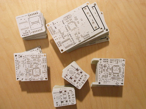
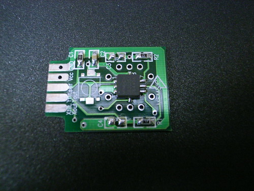
First job was a simple one. I have a bunch of Memsic MXC6202xJ two-axis accelerometers in a tiny LCC8 package, and a simple evaluation printed circuit board. The board had enough solder on the pads so I didn’t have to add any paste or anything.

I lined up the chip on the pads of the PCB and turned up the heat to around 350 degrees and waited..

Skillet Reflow

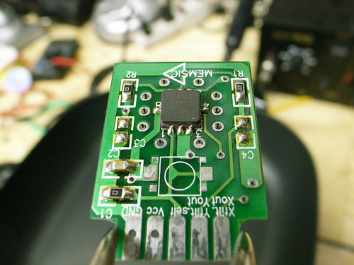
In short order, the solder greyed, went molten and the chip took hold. I gave it a light tap with a tweezer and it fell right in place. Lowered the heat and the solder set and that was that. Terribly easy!

I had to solder a few wires to the edge connectors on the PCB to make set it up for some prototyping. I guess I put too much heat on one of the pads — it was tricky to get the wire lead to hold to the edge connector pad, so I used a hemostat. I guess it torqued a bit and the pad went ahead and lifted off of the PCB, damnit.

Blown Pad

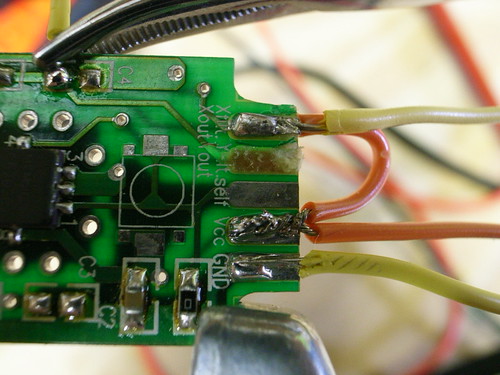
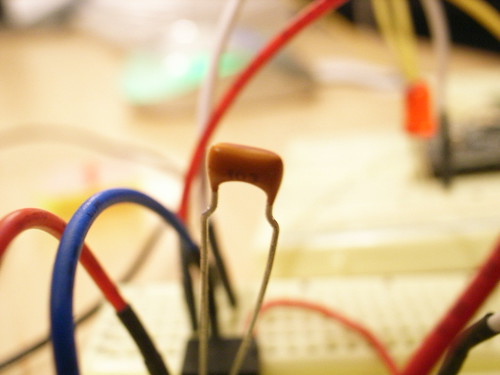
Fortunately, the other side of that particular trace went to a pad for an optional capacitor, so I could solder to that.

No-Lead, Room Temp Solder Paste

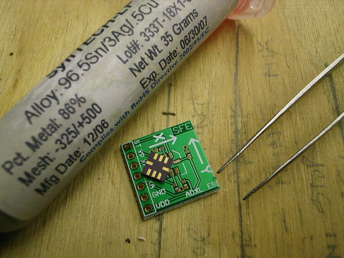
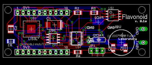
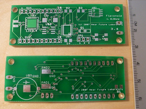
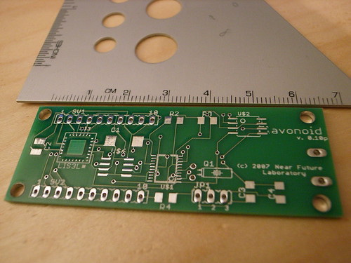
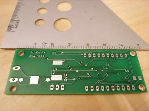
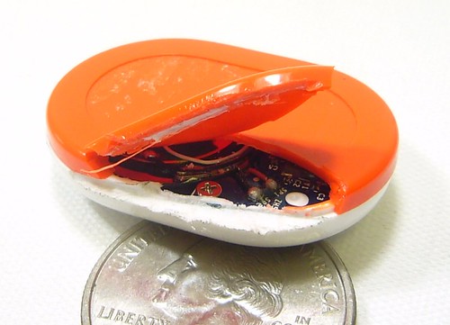
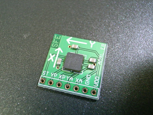
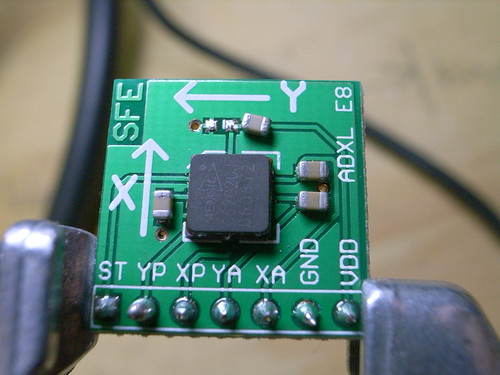
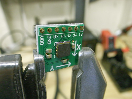
Here’s another quick surface-mount part I tossed together. It’s an improvised break-out board for mucking with the same Memsic MXC6202 dual-axis accelerometer as above. That board above — sold as an evaluation platform directly from Memsic — is pretty lousy if you ask me. $10.95, it doesn’t match up with its schematic, pads came off, it had an edge connector (for what?) when headers or a simple solder tail seems more appropriate for evaluation. Anyway..I had some boards for evaluating another chip with the same LCC8 footprint, so I just improvised.

Here I applied my own solder paste (the previous board had blobs of solder already on the board), and used this no-lead, no-clean paste manufactured by SynTech that supposedly doesn’t require refrigeration (I refrigerate it anyway.) I got it from Stencils Unlimited. The next-day shipping cost as much as the product itself..and they make you ship next day so the goo doesn’t sit in a baking hot UPS facility and get ruined.

Applicators

The solder-paste they sent me came with a plunger for the applicator and a couple of simple, conical applicator tips, but I already had a selection of applicators with a couple different sized metal tips. I guess you could snip the plastic applicator tips to the size you wanted and things would be just fine. I chose to use a narrow gauge metal tip this time, from the small kit of tips I got from Zeph, the applicator tip king.

Too Much Goo

Here’s my little board all laid out with too much solder paste applied. I’d end up doing this one over — it made me nervous. I tapped the part while it was in the skillet and it slid over — I could see that the paste had smeared all over the place and was likely going to short pins out. I just removed the part, wiped the board clean and re-applied a much smaller quantity of paste. It would’ve been a good idea to let the paste get a little warmer so it was more viscous before I started working. This stuff was running a bit thick, which made it harder to apply very small dots of paste.

Reflow Skillet

Here we are in the skillet — the solder has pretty much reflowed. I’d later find out that the two capacitors off of pins 6 and 7 were (a) the wrong part and, (b) supposed to be pull-up resistors and, (c) unnecessary because I had my own pull-up resistors on the breadboard. The upside? This was good practice doing some rework — I had to remove the parts to make the board work. I used the hot air station I got from Spark Fun. It’s relatively slow going to blow air and melt the paste, but it definitely works. Patience is required. I had to resist the urge to just crank the heat way up and blow like the Santa Ana’s — this hot air station will quickly melt the PCB. It’s super hot. I’m completely paranoid about this hot air station — it’s got no safety or auto-off or anything. I mean..I unplug the whole thing when I leave the laboratory. Turning the power switch to off just somehow doesn’t seem to be enough.

Quick Fix

I also found that the bypass capacitor here was hiding a short, probably because I put on too much solder paste and it likely smeared under the there. I removed the part, wiped the area clean, and then reflowed it, this time using hot air directly on the device, as opposed to throwing the whole thing in the skillet which just would’ve heated everything up and that’s no good.

Attaching Breakout Header

That’s that.

Here is my growing collection of links related to technique, supplies, etc. for backyard surface-mount technology work.

#include
#include


// TWI (I2C) sketch to communicate with the Memsic MXC6202J accelerometer
// Using the Wire library (created by Nicholas Zambetti)
// http://wiring.org.co/reference/libraries/Wire/index.html
// On the Arduino board, Analog In 4 is SDA, Analog In 5 is SCL
// These correspond to pin 27 (PC4/ADC4/SDA) and pin 28 (PC5/ADC5/SCL) on the Atmega8
// The Wire class handles the TWI transactions, abstracting the nitty-gritty to make
// prototyping easy.

void setup()
{
  Serial.begin(9600);
  Serial.println("Naah??");
  Wire.begin(); // join i2c bus (address optional for master)
}

void loop()
{

  byte x_val_l, x_val_h, y_val_l, y_val_h;
  int x_val, y_val;
  //byte in_byte;
  // transmit to device with address 0x1D
  // according to the LIS3L* datasheet, the i2c address of is fixed
  // at the factory at 0011101b (0x1D)

  Wire.beginTransmission(0x10);
  Wire.send(0x00); // CTRL_REG1 (20h)
  Wire.send(0xF0);
  Wire.endTransmission();

  delay(100);

  Wire.beginTransmission(0x10);
  Wire.send(0x00); // CTRL_REG1 (20h)
  //Wire.send(0x00); // address to start reads
  Wire.endTransmission();

  /*
  Wire.beginTransmission(0x22);
  Wire.send(0x00); // CTRL_REG1 (20h)
  Wire.endTransmission();

  Wire.beginTransmission(0x24);
  Wire.send(0x00); // CTRL_REG1 (20h)
  Wire.endTransmission();
  */

  Wire.requestFrom(0x10,5);
  while(Wire.available()) {
    Serial.print(Wire.receive(), HEX); // drop the internal register on the floor..
  }
  Serial.println("****");

  if(Wire.available()) {
    x_val_h = Wire.receive();
  }
  if(Wire.available()) {
    x_val_l = Wire.receive();
  }
  if(Wire.available()) {
    y_val_h = Wire.receive();
  }
  if(Wire.available()) {
    y_val_l = Wire.receive();
  }
    x_val = (x_val_h << 8); x_val |= x_val_l;
    y_val = (y_val_h << 8); y_val |= y_val_l;
  Serial.print(x_val_h, HEX); Serial.print(" "); Serial.print(x_val_l, HEX); Serial.print("n");
  Serial.print(y_val_h, HEX); Serial.print(" "); Serial.print(y_val_l, HEX); Serial.print("n");
 Serial.println("===");

Wire.endTransmission();

  delay(200);
}

Continue reading Reflow Skillet

Printed Circuit Board Fab Houses — A Few Reviews

So, I’m at the point with the Flavonoid project that I need to start getting printed circuit boards made. (The printed circuit board includes an accelerometer, a real-time clock, touch sensor, and a bit of EEPROM memory, if you want to know.) A fair bit of the break was spent schooling up on Eagle, doing layouts, making mistakes and that sort of thing. (It’s remarkably full-featured for a free product and, despite a few quirks, does what it says it will do. Plenty of activity in the forums and help is quick to come when I’ve gotten in trouble.)As I closed in on a design I thought was close enough to gold to send off, I started poking around various forums to find out what operation might be suitable for small (1-10 piece) runs.

It turns out that most of the places you’ll hear about won’t do fewer than 5 pieces, and they’ll charge you for it, too. By way of example, I considered trying Advanced Circuits as the Spark Fun FAQ suggests them if you’re in a pinch for time. It’d have to be more than a side-project financed with my own wallet to use them, but maybe they’re better for big projects. (I compare them to the other two board houses near the end of this post.)

The one great exception is Batch PCB, the operation started up by the Spark Fun guys. They’ll do single pieces for, like..$2.50 per square inch. In my limited experience, that’s a great deal. In exchange, you’ll have to wait a bit longer to get your boards back — I think they’ve worked something out with their guy in China so that the numbers work out to get that kind of pricing.

The two places I’m trying are Batch PCB and PCB Fab Express. I picked PCB Fab Express because they had something they refer to as a special for prototypes, but it’s still pretty expensive (but less expensive than other places that’ll turn something around in under a week). I’m doing this so I know what my options are in the future. I can imagine times when waiting a couple of weeks is fine, and other times when I’d like to have something in a few days.

Batch PCB

This is Spark Fun‘s boardhouse operation, which I’d generally just use without even thinking twice, and I have, basically. The one small thing that makes it not necessarily a slam-dunk is the turn-around, which will be at least 10 days. But, that’s probably just fine, except sometimes I feel anxious. But, you know — it’s not like I have customers waiting for product or anything..just me. So, that aside, the Spark Fun guys are friends of the cause and so I support them whenever possible. What you’ll get are 2-layer (seems like they’re doing up to 4 now) boards with pretty much everything. No need to count vias or stuff. Silkscreen on both sides. 8 mil wires and a recommended 10 mils spacing. You can order one board if you want, which is fantastic (as opposed to most other places that make you order 5 of something for which you need only one, or which isn’t 100% yet, so you may end up getting 5 drinks coasters for your $100.) You can put more than one design in your board and just score the two, which can save you some trouble. They have one thing that most places don’t even think to provide — a simple, short-and-sweet Eagle tutorial on preparing your Gerbers. They have a hopped-up forum, where answers to your questions come back pretty lickity-split. Their DRC bot sends you a decent design review summary within a few minutes of uploading your Gerber .zip file (I’m still waiting to get back the DRC from PCB Fab Express, which I sent in a couple of hours ago.)

Flavonoid PCBs from BatchPCB

Flavonoid PCB’s just arrived from BatchPCB.com

All-in-all, this is the place to go if you can wait a couple of weeks for your parts. The PCBs you see above were sent in on December 28, and arrived on January 18. Considering generally delays during the holidays, and that Boulder (where those guys are) got socked in by a nasty blizzard, I’d say that’s satisfactory. Total cost for four boards with express shipping was $49.92 Compare to $82.95 for PCB Fab Express, five boards, five days, super-saver shipping. If you’re in a rush or just hopped-up and heads-down in a project, I’d guess the extra $30 is nominal. Note that PCB Fab Express won’t silk screen the back of the board, but that’s not such a big deal in most situations, particularly for prototyping.

One thing I noticed about the boards is that they’re not all 100% the same footprint. By this I mean that the way they were cut out of the larger panel (with probably lots of other people’s boards on it) resulted in slightly different dimensions. I mean, slightly. If you put the boards together like a sticks of gum in a pack, you can tell that some are slightly larger/smaller along the various dimensions. One even seemed slightly curved. This could be an issue if the packaging in which these boards are placed has critical sizing issues. But, it’s ever so slight — nothing that a fine file couldn’t smooth out, if it even caused a problem. (I’m talking about something that’s noticeable if you eyeball it, and measuring, it seems to be about 1mm or less discrepency in size.)

Summary: BatchPCB.com, four boards, silk screen on both sides, 14 business days turn-around, with a blizzard interfering, $49.92 with shipping.

Note that BatchPCB turn-arounds get shorter the more work they do as a company. Presumably, they are able to fill panels sooner and ship whatever minimums they need to their guy in China. Now (January 19) they say they’ll panelize a board in four days, so the turn-around is likely closer to 10 days or thereabouts. That’s fantastic. I also found BatchPCB to be much more “user-friendly”, as is generally the way with the Spark Fun team. (Their tutorials are excellent, particularly the one on does and don’ts for prototyping, all based on real experiences. Don’t forget their surface mount technology tutorials, too, found here. I had two situations where I needed to cancel an order I had submitted. Fortunately, it hadn’t gone too far into the cycle and they could delete the order. Their DRC bot is also quick and provides some useful graphics to give you a sanity check about what precisely you’re submitting.

PCB Fab Express
Okay, this operation seemed a little weird from the get-go, mostly because I got a call about 20 minutes after I created an account. (That sort of bothers me.) But, I talked to the sales guy and was assured that when I submitted by Gerber zip file, I’d get a design review check done and an email back. I submitted my Gerber zip file and must’ve misread something somewhere because my order was put “in process.” The board, my fault completely, had a ground plane copper pour that seemed okay, but I noticed that there were these friggin’ vias going through it. It was just all messed up, but I fixed it in about 3 minutes. Unfortunately, if they even had a DRC, it didn’t catch this (not sure it would’ve, even though it basically meant that nets that shouldn’t connect were connected.)

I tried to cancel it (calls and emails) but probably between a mix of my not being as attentive to what I clicked on and the holidays, there was no way to get the order out. I think there’s a problem in the Gerber I sent them, and I’m a bit surprised I didn’t get a DRC email or anything, but..well..I guess chalk that up to experience. (Update — it seems fine after eyeballing the boards I got.) Their prices are a bit more reasonable than other operations for the turn-around — 5 boards, 5 days, $82.95 with tax and “super saver” shipping. They’ll do a finer line spacing than is typical (6 mils). The largest drill hole they’ll do is 246 mils plated, which is fine, only sometimes a mounting hole might be larger, possibly. They have some restrictions on the average number of holes per square inch, which could be annoying if there are lots of vias or whatever. Two-layers, but no silkscreen on the bottom, which one can typically live with for a prototype.The boards just came in, which is exciting. The problem I thought I was going to have didn’t appear for some reason. Unfortunately, I over-wrote the board file from Eagle and so I can’t double-check what I sent them. (I could look at the Gerber’s, though.)

I don’t have all the parts yet, but just a cursory look-see and I thought of a few notes to think about for any redesign.

Flavonoid PCB Prototype Recto

PCB Prototype Recto from PCB Fab Express Flavonoid PCB Prototype Recto

PCB Prototype Verso from PCB Fab Express. Notice there’s no silkscreen on the bottom.* First, some of the vias are unnervingly close to the pins of the DS1306. I’ll look for that in the future and put in a via keepout or something.

* Second, the crystal for the RTC I pulled from the crystal library. The pads for the package aren’t much bigger than a via, and there’s not much of a pad to speak of on the thru-hole. It might be just as well to find an SMT pad for it, or perhaps there’s a package in the crystal library for a surface-mount device.

* The mounting pin for the coin cell battery holder on the back is a bit close to the VBAT pad I put back there. I’m not sure if that mounting pin is connected to anything electrical in the coin cell holder, but I need to check just to be sure.

Summary: Quick turn-around. No hand-holding despite getting a sales call and promise of an email once I submitted. $82.59 with shipping for 5 boards, $16.52 per board, $6.19 per square inch. They took normal Gerber’s RS274X. I used the CAM processor user language program that Spark Fun provides for Eagle in their tutorial.

Advanced Circuits
Expensive and no real reasonable hobbyist pricing for a prototype option. This is probably “okay” for some situations, but certainly not for a hobbyist who’s just looking to get some boards done. No fault, no blame. Just thought I’d add it in since I went through the trouble of checking them out, but I won’t order from them.For comparision, I got a quote from Advanced Circuits for my test case — this Flavonoid PCB that you see above. For a “prototype” run, five boards in 3 days (the longest possible turn-around), it was $47 per board, or $235 without shipping. Their best value deal is 2 days, $57 per board. One day is $61 per board, and same day is $117 per board. Their production pricing — 50 units, say — is $5.86 per board in 2 weeks, or $7.57 a board in 3 days. So, roughly speaking, BatchPCB (described below) is priced in the same ballpark as Advanced Circuits’ production prices, even at single units. My BatchPCB boards came in 2 weeks and cost $7.50 a board ($2.50 per square inch, rounded up.)

Conclusion It’s hard for me to think why I would not use BatchPCB unless I really needed boards quicker than two weeks. If I need something in under a week, I’d go with PCB Fab Express. And, if I really am in some kind of project where I need dozens of printed circuit boards, I’d almost certainly go with BatchPCB — it’s just the best value.

If anyone has any suggestions of other board houses, please drop a line.


R0014191

Update! I’ve been using Gold Phoenix when I need more boards as soon as possible — under a week. I haven’t completely run the numbers, but it’s pretty clear that for more than 10 boards or so, they’re the place to go to. If I need just singles of boards and can wait, I’ll use BatchPCB. I have a review of Gold Phoenix here.
For $89 (special summer deal pricing) you can get 1000 sq centimeters of PCB. When I put six designs on this size, I got 10 of each back. That’s 60 total boards. I paid extra to have some special features like white soldermask and black silkscreen and a $30 tax for multiple designs. Still, it seems like a great deal. Turn-around was under about 12 days.

Spark Fun Cracks Open a Nike+

Nike+iPod-2

I’ve been waiting for someone else to do this. I got one over a month ago, but haven’t taken the time to hammer it open. I’m glad more adept reverse engineer types went ahead and did it.

For those who don’t know, this is a brilliantly simple fitness pedometer, of sorts, that outputs its data to an online sort of display of how far you’ve run. It’s very game-like, in many ways — you can compete against friends and see your performance as compared to theirs. Great for informal challenges and such. Sad part is that this is a Nike product that only fits in a Nike shoe. I’m sure it drives sales and such all..just wishing it was more open in that regard.

Cabel Maxfield Sasser has a bit of a write-up on the Nike+ based on his experiences with it. It’s pretty good, and shows some of the game aspects of the product.

I appreciate the low-impact style gaming — it’s ambient, based on an activity you’re engaged in anyway, so why not? It’s not like investing in a $700 PS3 to sit on the sofa all day.

More at the Spark Fun Electronics site.

Quick Note on Touch Sensors — QT113/118

103
103, .01uF, light contact trigger

I need a touch sensor for a couple of projects, and the Qprox QT113 seems to be the way to go, particularly for interfacing with an Atmel processor. It’s easy to work with, and hooks-up with only a bare minimum of extra stuff. All you need is a resistor and capacitor and a bit of wire or trace to compose the sensor.

Tom Igoe documents most of the details here.

There’s one wrinkle in my project, and that’s figuring out what value I should use for the capacitor — which is basically what controls the sensor’s, you know..sensitivity. So, I tried two values, .01uF and .1uF, to find out what the thing means by “touch.” (I’m looking at something that is more ambient than a full-on, bone-jarring style touch — something closer to “nearby”.)

R0011753
Experimental..”apparatus”

Rough experiment. I used about a 24″ bit of test lead hooked up to the sensor pin of a QT113. I coiled it into a very loose 3″ diameter loop, about two wraps. Nothing precise here. I placed it on the surface of a 1″ thick wooden desk surface.

With the .01uF capacitor, I basically had to make physical contact, albeit light, with my open palm over the loop to get it to trigger. A single finger placed on a bit of loop lightly, wouldn’t trigger it, but if I put two or three fingers, it would trigger.

With the .1uF capacitor, I could trigger the sensor by hovering my palm a half inch or more above the coil. I could also trigger it if I placed my palm underneath the desk surface where the sensor coil was sitting.

So, 104/.1uF will give more sensitivity to the degree of a half or so inch of air between a loop sensor, while 103/.01uF requires light physical contact with the sensor.

This is what the specification sheet means by “higher values of Cs increase gain”

Short note on the QT113 and QT118 — these parts each have a varient, the “H” part — QT113H and QT118H. The variant basically inverts the logic level of the output, so it goes high (logic 1, or VCC) when it’s triggered. Other useful notes about these devices is that they can be configured to have a sustained output when triggered, or to stay on for 10 seconds or 60 seconds. The QT118 also offers a “toggle” mode so that each trigger flips the state, and a pulse-mode output.

Arduino and the Two-Wire Interface (TWI/I2C) Including A Short Didactic Parenthetical On Making TWI Work On An Arduino Mini

I have been using the Arduino and Atmel microcontroller’s generally using the SPI (serial-peripheral interface), but decided to look at the two-wire (a.k.a. I2C) interface as well. I’m doing this partially because it would be good to know how it works, but also because it’s electrically more compact. It only uses two-wires, rather than the four required for SPI, so schematic designs and board layouts become a bit more manageable. The trade-off is a little bit more complicated protocols semantics, but nothing out of control. (I’m also looking at using a two-axis accelerometer that’s much less expensive than the three-axis one I’ve been using – $4 versus $15. For some experiments, two-axes may be perfectly fine, and I’m happy to save the $11.)

The first step was making sure the Arduino would handle the TWI – there’s pretty much no reason it shouldn’t, because the Atmega8 certainly handles it. So, the next step was finding out how best to handle TWI transactions.

To do this, I consulted the Atmega8 specification sheet, which has a pretty thorough explanation of the protocol and the implementation details on the Atmega8. (There are also a couple of useful application notes available here and here.) It’s so thorough that I had to print it out. I got a pretty good understanding of how it works but before I started coding, I noticed that there were some TWI libraries both in avrlibc and in the “Wire” library in Wiring.org happens to be packaged as a “sanctioned” external library for Arduino, so that was pretty much that.

Nicholas Zambetti, who wrote the Wire library, pretty much told me it should work with no problems, and he was pretty much right. No problems. His library abstracts the TWI innards really nicely, so I don’t have to muck with any Atmega registers or anything of that sort.

I hooked up my Arduino to a handy accelerometer for testing. (I’m still using the expensive LIS3LV02DQ.) Analog In 4 goes to SDA, and Analog In 5 goes to SCL. I have pull-up resistors on those lines, but Nicolas explains that his library enables the internal pull-ups on the Atmega, so I can probably pull those from my breadboard. Either way, it’s working just fine, even with the external pull-up resistors. (I’m using 4.7k resistors.)

Arduino Mini TWI (I2C)

(I also found in one weird situation that I had to explicitly clear the clock prescaler to get the UART functioning properly. This was while getting TWI working on an AT90USB1287 – TWI worked fine, but the UART was spitting out garbage. On chips where the clock prescaler can be set through the fuses, it’s important to verify that the prescaler isn’t hard wired to divide the clock. This’ll cause anything that is dependent on timing to potentially be off kilter. In my case, the UART was expecting an 8MHz clock to determine timing and baud rate, but the clock was being divided in hardware – not even in the firmware.)

Wire/TWI (I2C) on the Arduino Mini

Getting TWI working on the Arduino Mini (Although the Arduino and Arduino Mini share a name, they don’t share the same processor. The Arduino Mini uses an ATmega168, while the Arduino..normal.. uses an ATmega8. You’ll need to recompile/re-“verify” the Wire library files in order to get TWI to work on the ATmega168/Arduino Mini. There’s a thing or two you’ll have to do by hand to get this to work, and you’ll need to do it each time you move code that’s using the Wire library to a different processor. In other words, when you decide to port the code to the ATmega8, or you put an ATmega16 in your Arduino, or whatever — you’ll need to recompile these libraries. Here’s the drill:

Navigate in a file browser or command prompt to the root of your Arduino file hierarchy. Then go into:

lib/targets/libraries/Wire/
delete Wire.o

lib/targets/libraries/Wire/utility
delete twi.o

Once you’ve done this, make one modification to the header file twi.h in lib/targets/libraries/Wire/utility. Look around line 27 for a commented out line like this:

//#define ATMEGA8

Un-comment it (take out the “//” in the front.) This’ll ensure that the internal pull-up resistors on the ATmega8 are enabled when you’re developing for the normal Arduino. You’ll only need to make this change to twi.h once and for all. Future builds of Arduino should have this fixed.

For those who are curious — pull-up resistors are required on the TWI lines — SCL and SDA. You may use your own external pull-ups, but enabling the internal ones saves you the hassle. But, I don’t think you’ll do much harm if you have the internal one’s enabled and use external ones. But, generally you’ll want to avoid having both internal and external pull-ups.)

Anyway. These modifications described above should get TWI working on the Arduino Mini.)

Here’s the code I wrote and ran:

#include

// TWI (I2C) sketch to communicate with the LIS3LV02DQ accelerometer
// Using the Wire library (created by Nicholas Zambetti)
// http://wiring.org.co/reference/libraries/Wire/index.html
// On the Arduino board, Analog In 4 is SDA, Analog In 5 is SCL
// These correspond to pin 27 (PC4/ADC4/SDA) and pin 28 (PC5/ADC5/SCL) on the Atmega8
// The Wire class handles the TWI transactions, abstracting the nitty-gritty to make
// prototyping easy.

void setup()
{
  pinMode(9, OUTPUT);
  digitalWrite(9, HIGH);
  Serial.begin(9600);

  CLKPR = (1<<clkpce);
  CLKPR = 0;

  Wire.begin(); // join i2c bus (address optional for master)
  Wire.beginTransmission(0x1D);
  Wire.send(0x20); // CTRL_REG1 (20h)
  Wire.send(0x87); // Device on, 40hz, normal mode, all axis's enabled
  Wire.endTransmission();

}

void loop()
{

  byte z_val_l, z_val_h, x_val_l, x_val_h, y_val_l, y_val_h;
  int z_val, x_val, y_val;
  //Serial.println("hello?");
  //byte in_byte;
  // transmit to device with address 0x1D
  // according to the LIS3L* datasheet, the i2c address of is fixed
  // at the factory at 0011101b (0x1D)
  Wire.beginTransmission(0x1D);
  // send the sub address for the register we want to read
  // this is for the OUTZ_H register
  // n.b. supposedly masking the register address with 0x80,
  // you can do multiple reads, with the register address auto-incremented
  Wire.send(0x28);
  // stop transmitting
  Wire.endTransmission();
 // Now do a transfer reading one byte from the LIS3L*
 // This data will be the contents of register 0x28
 Wire.requestFrom(0x1D, 1);
  while(Wire.available())
 {
   x_val_l = Wire.receive();
 }
 Wire.beginTransmission(0x1D); Wire.send(0x29); Wire.endTransmission();
 Wire.requestFrom(0x1D, 1);
 while(Wire.available())
 {
    x_val_h = Wire.receive();
 }
 x_val = x_val_h;
 x_val <<= 8;
 x_val += x_val_l;

 // Y Axis
 Wire.beginTransmission(0x1D); Wire.send(0x2A); Wire.endTransmission();
 Wire.requestFrom(0x1D, 1);
 while(Wire.available())
 {
    y_val_l = Wire.receive();
 }
 Wire.beginTransmission(0x1D); Wire.send(0x2B); Wire.endTransmission();
 Wire.requestFrom(0x1D, 1);
 while(Wire.available())
 {
    y_val_h = Wire.receive();
 }

 y_val = y_val_h;
 y_val <<= 8;
 y_val += y_val_l;

// Z Axis
 Wire.beginTransmission(0x1D); Wire.send(0x2C); Wire.endTransmission();
 Wire.requestFrom(0x1D, 1);
 while(Wire.available())
 {
    z_val_l = Wire.receive();
 }
 Wire.beginTransmission(0x1D); Wire.send(0x2D); Wire.endTransmission();
 Wire.requestFrom(0x1D, 1);
 while(Wire.available())
 {
    z_val_h = Wire.receive();
 }

 z_val = z_val_h;
 z_val <<= 8;
 z_val += z_val_l;
  // Set up to read the next register
  // Supposedly, if you set the most significant bit of
  // the register address to 1, you can do a multiple read,
  // with the register address auto-incrementing. This way, you
  // don't have to do another write — specifying the next register —
  // before reading the next register value. This would be very good, but
  // with a cursory attempt, I have yet to make this work.
/*
    Wire.beginTransmission(0x1D); // transmit to device #4
  Wire.send(0x2C);        // read outx_h
  // stop transmitting
  Wire.endTransmission();
  Wire.requestFrom(0x1D, 1);
 while(Wire.available())
 {
   z_val_l = Wire.receive();
 }

 z_val = z_val_h;
 z_val <<= 8;
 z_val += z_val_l;

  // z axis acceleration, all set.
  // Perfectly still and with the z-axis parallel to the ground, it should be about 1024-ish
  // (I find in practice it is around 1019.)
  // When the z-axis is orthogonal to the ground, it should be zero.
  // 1024 is +1g acceleration, or normal gravity
  // 2048 is +2g
  // 0 is 0g
  Serial.println(z_val, DEC);
*/
Serial.print(x_val, HEX); Serial.print(" ");Serial.print(y_val, HEX); Serial.print(" "); Serial.println(z_val, HEX);
delay(100);
}

Technorati Tags: ,

Flavonoid Notes #2

Nicolas sent me information about this DS-compatible pedometer toy called Tekuteku Angel Pocket Pedometer, which looks very cool.

l_p1004543059

Hudson Soft has created a new pedometer game where the weight of onscreen characters fluctuates depending on the number of steps taken. As additional encouragement, Tekuteku Angel Pocket, displays messages of its screen such as — Nice walking!” if you’re doing well. Furthermore, the pedometer can be hooked up to your Nintendo DS using the DS Tekuteku Diary in order to keep track of walked steps along with calorie info and other health data. The pedometer and diary will go on sale on 21st December for 5,229 yen (£23/$44), and later in January, supposedly, in the U.S.

You can pick up a ice blue one or a pink one at Yesasia.com.

via www.plasticbamboo.com/2006/11/13/tekuteku-angel-pocket-pe…