Not the most exciting thing, but an interesting challenge here. I’m trying to get a Parallax Propeller chip to behave nicely as an TWI/I2C slave with the idea that I’d like to create a pretty much black-box interface that’ll allow a TWI/I2C master to control it for stuff. Ultimately I’d like to use the Propeller in the PSX project. It’ll sit in between a Playstation 2 and a normal Playstation controller, and be available as a TWI/I2C slave, so that another device, that doesn’t really care to figure out how to talk to a Playstation 2 or its controllers can make the PSX box with the Propeller in it emulate, for the Playstation, certain button presses, etc. Or, it could “read” over TWI/I2C from the PSX box and find out what the real controller is doing. Or, it could just read or write from a special TWI register address to make the PSX box (with the Propeller in it) just do a “pass-thru” so that the signals just go straight through as if there were nothing in between.
That’s the theory. In practice, setting up this test jig took more time that I would’ve thought.
First of all, the target for something controlling this box is an Arduino. It’s got a nice library that Nicholas Zambetti created to do TWI/I2C communication, so that part is fairly easy for beginners to play with doing weird things to control their Playstations.
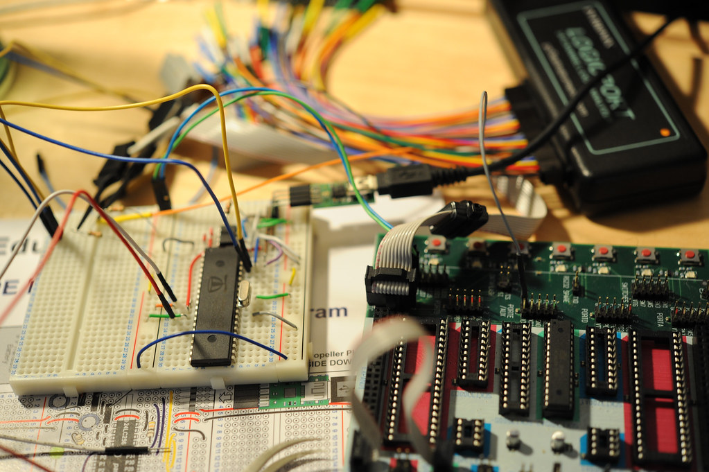
Thing of it is, well..a few things. First, the Arduino runs at 5v and 16MHz. The Propeller was created using a CMOS process that wants no more than 3.3v nominally, and 3.6v at the most. 5V can be done with some series resistors to limit current, evidently. Probably works fine, but may not be that great for a $12 chip over a stretch of time — for testing, probably you can get away with this, but.. I had hoped to get a PCA9306 bidirectional level shifter on a break out board (which I subsequently did..), and had a bunch..and some break out boards I thought it’d fit on, but the packages for this thing are smaller than I thought. Oh well.
Alternate plan. Put an Atmega168 on an STK500. The Atmega168 is the same microcontroller found in the (5 volt, 16MHz) Arduino. Now, just turn the voltage on the STK500 down to 3.3v, right? Yep, for a start. Unfortunately, the Atmega168 doesn’t want to clock at 16MHz at that voltage according to the electricals in the specification sheet. It’ll do 8MHz, but not 16MHz. Well enough. So, I set the fuses on the chip to use the internal clock, unset the CLKDIV fuse so there’s no internal divider and it’s running at 8MHz.

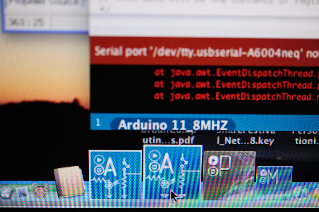
Awesome. Now I can code simply in my Arduino IDE, compile and then upload like normal, right? Nope. Remember, the Arduino IDE compiles for the Arduino board, in most cases. (There are a few new boards added to the board selector menu item, but not for my whacky rig..) In my case, I have an Atmega168, so that’s good. But, I’m running it at half the clock speed of a normal Arduino — 8MHz instead of the usual 16MHz. So, any code compiled in the Arduino IDE will be expecting a clock speed of 16MHz. Everything will run half as fast as expected and, seeing as I’m doing clock-y kinds of things, like serial clock synchronous communication aka TWI/I2C, I’d probably be setting myself up for some weirdness. (Didn’t try for the weirdness. Just wanted to do what I thought would work right off.)
(Here are some instructions on making more subtle adjustments to the Arduino IDE for making what I’m describing a lot easier. Thanks to David Mellis for pointing this out!)
The only way to get the Arduino IDE to compile for another clock speed is, to the best of my knowledge, digging into the file tree and mucking by hand with the Makefile. From the Arduino application directory, I went into hardware/cores/arduino and changed F_CPU in the Makefile to 8000000. But, I didn’t want to forget that I’d done this and cause myself headaches with other projects, so I copied my Arduino IDE into a whole new directory. Now I have an 8MHz version of Arduino.
Okay, all set? Code compiled, click upload to board?
Well, not quite. Of course, the STK500 isn’t an Arduino so getting compiled .hex files onto it isn’t through the usual drill of clicking the “Upload to Board” button. What I have to do is boot up the free IDE that the Atmel people provide called AVR Studio. It’s their IDE. You can connect it fairly easily to the win-avr toolchain, which means you’re running GCC tools to build for the microcontroller. It’s free, so don’t complain. It runs on Windows, so only complain if you have serious religious issues, but even then, you’re putting that ahead of getting some work done. I just run it in Parallels and get on with things.
AVR Studio is able to connect to the STK500 over a USB-to-serial port. From AVR Studio you can adjust the voltage of the board, set fuses, a bunch of other stuff — and program any device that you put on there. What I ended up doing is clicking the upload button on the Arduino IDE, which creates a directory inside the project directory, which then contains the .hex file that I need to get on the Atmega168. Because I’m running Parallels on the same machine as the one running Arduino, I can share files, pointing to my source code directory as a shared, mounted drive in Parallels.
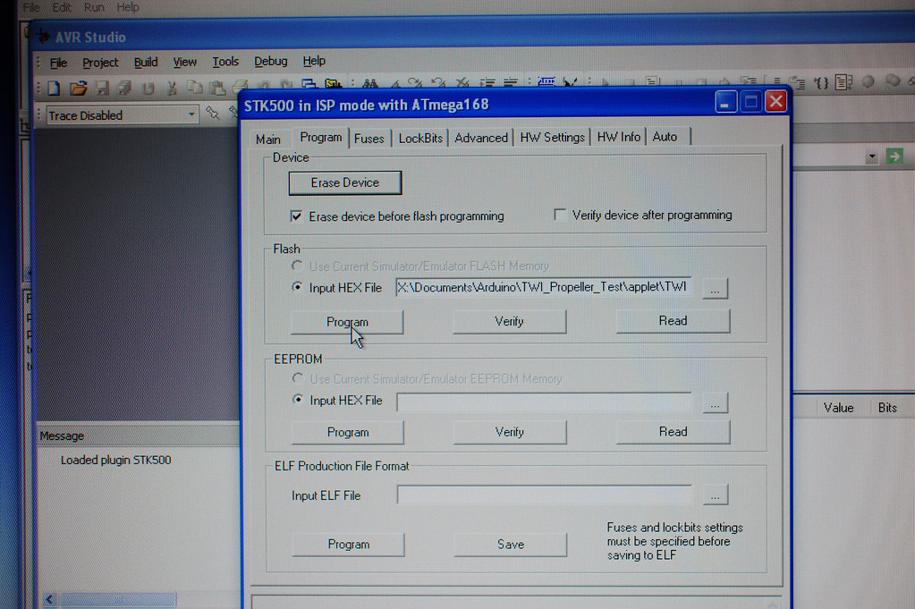
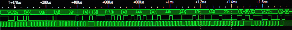
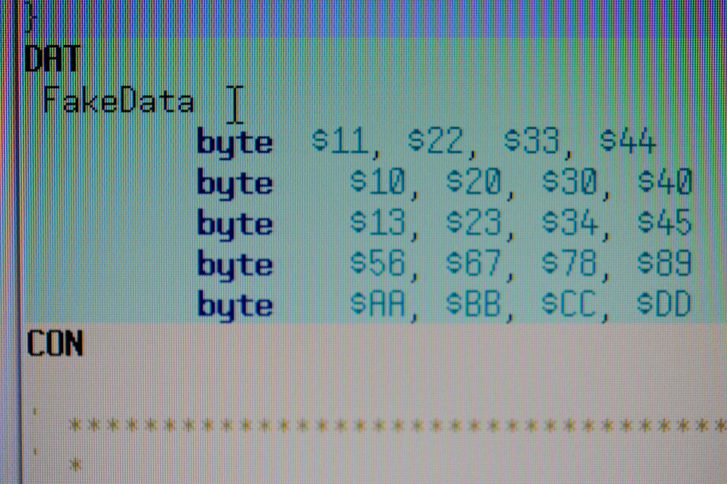
Now I can click Program in AVR Studio and have my Arduino code uploaded to that solo Atmega168. The code was just a simple TWI/I2C master functionality that reads and writes from the Propeller, which is sitting there, behaving like a TWI/I2C master listening to address 0x72h. This trace is actually the proof to myself that I can read/write from an external master to some shared memory on the Propeller. I need to be able to set values and read values to/from processes internal to the Propeller, as well as allowing an external TWI/I2C master do the same. So, in my Propeller “idle” code I write a 0xAA to the second “register” in my “register map”, changing the default values that are seen in my pre-loaded data map. You read this trace like this: the first write (W:72H at +478us) tells the Propeller what register address to read — in this case register address 0002h. That should be the second byte in this pre-loaded data map, except the Propeller code has a line in it that changes that value to 0xAA. (So, this is good — my register map is in shared memory, which means other processes internal to the device can read and write to it. Possibilities of race conditions and collisions, but this is all good fun and games.) The read I do from the Arduino is from the address just passed in via the write, and I read three bytes, so I get a sequence of data, beginning with register 2 and going up to register 5. (In the second image below, you can see that register 3 is 0x44, register 4 is 0x10, and register 5 is 0x20.)
That’s that.
// Arduino test code to read bytes from a device at address 0x72
void setup()
{
  Wire.begin(); // join i2c bus (address optional for master)
}
void loop()
{
// send the address we want to read from
Wire.beginTransmission(0x72);
Wire.send(0x00);
Wire.send(0x02); // here it is
Wire.endTransmission();

// read using the address just sent
// prepare to read three sequential bytes
Wire.requestFrom(0x72, 3);
Wire.endTransmission();
while(Wire.available()) {
 Wire.receive();
}
Yo!
The Lilypad entry uses an 8mhz clock. I know you already solved it , but i though i’d chime in.
Yep — it also runs at a lower voltage than the normal Arduino, which I realized in the midst of all this. It could be nice to have some around for debugging in these kinds of mish-mosh situations. Thanks for pointing that out Zach!
A couple of notes:
In the latest version of Arduino, you can edit the hardware/boards.txt file to create a new item in the boards menu for 8 MHz. Also, the LilyPad entry will compile things for 8 MHz.
You should also be able to upload directly using an STK500 from with the Arduino IDE. You can set the upload.using preference in the preferences file to the name of an entry in the programmers.txt file. See http://www.arduino.cc/en/Hacking/Programmer for more information.
Yep, I’ve been following that discussion. Didn’t know that it was in 011 though! Awesome! Thanks David.