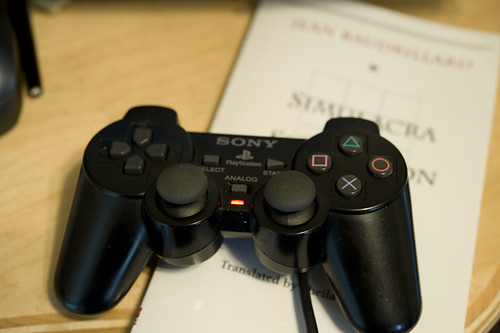
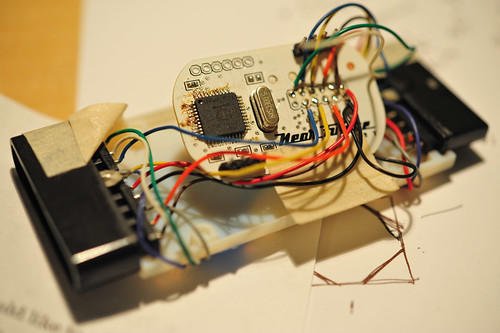
Continuing on my strange pursuit of designing weird interfaces that disrupt conventional game interaction rituals, I put together a bit more of my “PSX” project. You probably don’t recall, but this is the project where I’ve created a little “dongle” that can fool a PS2 (or Playstation 3, as it turns out..) into thinking that the dongle is actually a Playstation controller. You can also hook up a real Playstation controller to it and it can “read” the controller buttons and joystick and pass that data through, or do whatever you want with it. It appears as an TWI/I2C device to anything that talks to TWI/I2C devices..like my favorite TWI/I2C talking thing — the Arduino.
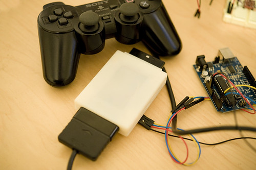
You can see here that the dongle — the white box with those annoying, huge Playstation connectors on either end, one male, one female — has four wires going into it. Those are for power, ground and the TWI signals, SDA and SCL. The power and ground are necessary because the Arduino (at least this one here) and the dongle run at different voltages. The Arduino is a 5V device, while the dongle is a 3.3V device, so there’s some level shifting going on inside there.
So, that’s all fine. It works, etc. But then the question that’s actually more intriguing than building the thing..what do you do with it?
Well, I have some ideas, including hooking up a bike to it and attaching a giant human form kick-boxing dummy to play old school fighting games. For some early fun and nonsense, I connected a Wii Nunchuck up to it to control Playstation games with Wii-y gestures and stuff. Which could be cool if I find the right game, or spend a little more time thinking things through rather than just writing and revising microcontroller firmware to make a TWI controllable device, and doing Catia to CAD-up and print plastic enclosures.
But, in the meantime, I decided to do an absolutely crucial bit of game science. Something that I am entirely sure is mulled over constantly, but never properly investigated. The question is best stated thusly: how long would it take the Little Prince to roll up an entire room based on a random path algorithm?
How long indeed. Well, short answer is a long time. I let it go for about 70 minutes, after which he had just 10 things to go in a particularly tricky location that required rolling across a narrow bridge. At this point, I took over..but check out the 8x speed video anyway!
Katamari Autonomy from Julian Bleecker on Vimeo
I wrote a quick little Arduino code for my PSX dongle to have the Little Prince roll forward and then, after a few moments, make a random directional change. (Or stop, take a load off and look around the world.)
This was all done by sending TWI commands to the appropriate registers in my little DIY Playstation 2 controller emulator. All the buttons and the joysticks can be emulated as to their state through a series of write-to registers. If there’s a controller stuck in the other side of the dongle, there are a complement of read-from registers so you can see if any of the buttons are pressed and how much the joysticks are displaced. (I set up an “escape” buttons sequence — pressing both L2 and R2 — to bring control back to the normal joystick so I could navigate menus or take control over, which I had to do after I realized, with four items left, the completion of cleaning the room would probably not happen before the universe ran out of steam.)
Here’s the Arduino code. Pretty straight forward Wire / TWI library stuff.
#include
#include "nunchuck_funcs.h"

#define is_bit_clear(a, n) (0 == (a & (1<<n)))
#define is_bit_set(a, n)  (1 == (a & (1<<n))

#define is_button_pressed(a, button) is_bit_clear(a, button)
#define is_button_released(a, button) is_bit_set(a, button)

#define BTN_SELECT 0
#define BTN_L3 1
#define BTN_R3 2
#define BTN_START 3
#define BTN_UP 4
#define BTN_RIGHT 5
#define BTN_DOWN 6
#define BTN_LEFT 7
#define BTN_L2 8
#define BTN_R2 9
#define BTN_L1 10
#define BTN_R1 11
#define BTN_TRIANGLE 12
#define BTN_CIRCLE 13
#define BTN_X 14
#define BTN_SQUARE 15

// register addresses in the PSX I2C device
#define W_BUTTONS_0 0x00 // (, ^, start, R3, L3, select
#define W_BUTTONS_1 0x01 // (square, x, o, triangle, R1, L1, R2, L2)
#define W_RIGHT_X 0x02
#define W_RIGHT_Y 0x03
#define W_LEFT_X 0x04
#define W_LEFT_Y 0x05

#define R_BUTTONS_0 0x12 // (, ^, start, R3, L3, select)
#define R_BUTTONS_1 0x13 // (square, x, o, triangle, R1, L1, R2, L2)
#define R_RIGHT_X 0x14 // a value from 0x00 - 0xFF
#define R_RIGHT_Y 0x15 // a value from 0x00 - 0xFF
#define R_LEFT_X 0x16
#define R_LEFT_Y 0x17

// I2C address of the PSX dongle
int psx_dongle_addr = 0x72;
int j;
void setup()
{
  Serial.begin(9600);
  randomSeed(analogRead(0));
  Wire.begin(); // join i2c bus (address optional for master)


// this is the control register. setting it to 1 means that
// we have to tell the PSX device what data to send to the
// Playstation2. Setting it to 0 means that it simply passes
// through the data from the controller to the PS2. We can
// read the state of the contorller at any time.

writeToAddress(psx_dongle_addr, 0x24, 1);
}

// we'll use count to figure out when to change direction
int count = 0;
int buttons;

// mode is used to indicate either "pass thru" where we can use the
// actually real human controller to control the PS2, or to generate
// data via the PSX dongle.
// pressing both L2 and R2 simultaneously toggles the mode
int mode = 1;
byte randomNumber;

void loop()
{
  byte val;
  count++;
  //Serial.println(count, DEC);
 // 0x70 shows up as either ID $20 or ID $E0 on Propeller

/*******************************************/
/*
  BTN_SELECT = $0001
  BTN_L3 = $0002
  BTN_R3 = $0004
  BTN_START = $0008
  BTN_UP = $0010
  BTN_RIGHT = $0020
  BTN_DOWN = $0040
  BTN_LEFT = $0080
  BTN_L2 = $0100
  BTN_R2 = $0200
  BTN_L1 = $0400
  BTN_R1 = $0800
  BTN_TRIANGLE = $1000
  BTN_CIRCLE = $2000
  BTN_X = $4000
  BTN_SQUARE = $8000
**/


// 0x00 write to BUTTONS_0, 0x12 read from BUTTONS_0
// 0x01 write to BUTTONS_1, 0x13 read from BUTTONS_1
// 0x02 write to RIGHT_X, 0x14 read from RIGHT_X
// 0x03 write to RIGHT_Y, 0x15 read from RIGHT_Y
// 0x04 write to LEFT_X, 0x16 read from LEFT_X
// 0x05 write to LEFT_Y, 0x17 read from LEFT_Y
//Serial.println(getButtons(), HEX);
//int buttons = getButtons();
//Serial.print(buttons, BIN);
//  passThruButtons();

if(count > 512) {
  count = 0;
}
//Serial.println(mode, HEX);

// get the buttons
buttons = getButtons();

// mode is used to indicate either "pass thru" where we can use the
// actually real human controller to control the PS2, or to generate
// data via the PSX dongle.
// pressing both L2 and R2 simultaneously toggles the mode
  if(mode == 1 &&
     is_button_pressed(buttons, BTN_L2) && is_button_pressed(buttons, BTN_R2)) {
    mode = 0;
    delay(1000);
  } else
  if(mode == 0 &&
     is_button_pressed(buttons, BTN_L2) && is_button_pressed(buttons, BTN_R2)) {
     mode = 1;
     delay(1000);
     }
 if(mode == 1) {
passThruAllAndShow();
 }
 if(mode == 0)
  {

  writeToAddress(psx_dongle_addr, W_LEFT_Y, 0x00);
  writeToAddress(psx_dongle_addr, W_RIGHT_Y, 0x00);
  passThruButtons();

  if(count == 512) {
    count = 0;

    randomNumber = random(1,5);
        Serial.print("FLIP! ");
        Serial.println(randomNumber, HEX);
    switch(randomNumber) {
      case 1: case 2: case 6:
        writeToAddress(psx_dongle_addr, W_LEFT_Y, 0x00);
        writeToAddress(psx_dongle_addr, W_RIGHT_Y, 0xAF);
        delay(500);
        break;
      case 3: case 4: case 5:
        writeToAddress(psx_dongle_addr, W_LEFT_Y, 0xAF);
        writeToAddress(psx_dongle_addr, W_RIGHT_Y, 0x00);
        delay(500);
        break;
          default:
         delay(500);
         break;
    }
  }

  /*
writeToAddress(psx_dongle_addr, W_LEFT_X, (float)map(nunchuck_accelx(), (float)0x48, (float)0xB0,
                (float)0x00, (float)0xFF));
writeToAddress(pssx_dongle_addr, W_LEFT_Y, (float)map(nunchuck_accely(), (float)0x48, (float)0xB0,
                (float)0x00, (float)0xFF));

writeToAddress(psx_dongle_addr, W_RIGHT_Y, (float)map(nunchuck_joyy(), (float)0x1D, (float)0xDF,
                (float)0x00, (float)0xFF));
writeToAddress(psx_dongle_addr, W_RIGHT_X, (float)map(nunchuck_joyx(), (float)0x1D, (float)0xDF,
                (float)0x00, (float)0xFF));
*/
}

delay(10);
}


//
int getButtons()
{
int result = 0x00;

result = readFromAddress(psx_dongle_addr, 0x13, 1);
//  Serial.print(result, HEX); Serial.print(" ");
result <> 8)); // MSB
  Wire.send((int)(addr & 0xFF)); // LSB
  Wire.send(data);
  Wire.endTransmission();
}

byte readFromAddress(int twi_addr, int addr, int bytes_to_read)
{
  byte rdata;
 Wire.beginTransmission(twi_addr);
  Wire.send((int)(addr >> 8)); // MSB
  Wire.send((int)(addr & 0xFF)); // LSB
  Wire.endTransmission();
  Wire.requestFrom(twi_addr,bytes_to_read);
  while (Wire.available()) rdata = Wire.receive();
  return rdata;
}


You should make the Arduino listen to the rumble pack messages and use those to know when you’ve bumped into something. That way, you could change directions in a more predictable (and better) way. (i.e. when you bump, go bacwards for 500ms, turn right for 200ms, then try going forward again, or something like that. )
You could also use “Roomba-esque” spiraling motion to try to clear an area of debris. (that would require analog outs, which you may or may not want to do) I think if you listen to the rumble messages, you’ll have about as much world knowledge as the Roomba does — all it has is a simple bump sensor on the front, and that’s what the rumble will tell you.
Hey, that’s a really good idea. I hadn’t yet integrated rumble messages from the console into the whole deal, but I should do that. Thanks for the suggestion!
Should be fun to use with fighting games to get the combos right =) Would love a video of that too ^^
Really, the thing to do here is to remove the brain from a Roomba and wire it into Katamari Damacy. It’s the Brain-in-a-Vat experiment brought from philosophy to the real world!
This has got some very exciting possibilities for disabled people:
http://switchgaming.blogspot.com/2009/07/one-step-closer.html
Do you think it’s possible?
Barrie
OneSwitch.org.uk
Sure, it is possible. I’m not entirely sure what the set up would be, though? The design of the components are so that you can make something other than a Playstation controller look like it is in fact a Playstation controller. It requires some additional hardware and firmware of course. But, for example, output from a normal computer could talk to this device which would then talk to the Playstation console. Something like this.
This looks really interesting! As an Arduino enthusiast I would love to see your “dongle” schematic. I can think of a bunch of awesome stuff that could be done with this.
That is awesome! Like Jordan, I would like to see the parallax schematic for this. Man, this thing on Street fighter 4 would be awesome for learning to counter those hard to defeat moves.
I’ll have to get back to this one at some point. There’s nothing especially complicated about the schematic — it’s a standard Propeller project, so the Propeller and it’s EEPROM, and then I put a voltage regulator and a level shifter for the I2C communication..that’s it. The rest is done in hairball firmware on the Propeller to emulate a Playstation controller and become an I2C device that the Arduino can talk to..the other funny bit is getting Playstation-type connectors, which are ugly and big. I should look into getting it to work with a PS3, too.
Awesome! I am excited to see that. Couldn’t you just use a ps2 to ps3 converter?
Yeah — I think that’s exactly what I’d try and do. I have a couple of them lying around. It will probably work — although who knows? I’m mucking with so much of an unpublished protocol and just assuming it’ll work is probably safe, but..