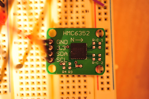
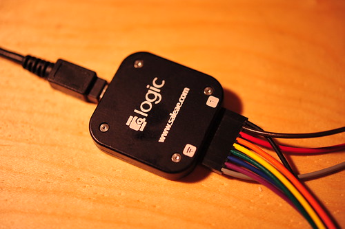
Two things that’ve been sitting on my bench for a good spell — this HMC6352 magnetic compass with an I2C interface, and the Saleae “Logic” logic analyzer. I figured I could combine the two together, showing how I used the Logic to check out the operation of the HMC6352.
First, the HMC6352 is a pretty easy to use magnetic compass with 0.5 degree accuracy. It’s all wrapped up nicely with a pretty normal I2C interface to a bunch of registers on the device, and command-driven queries for reading the compass heading.
The Saleae “Logic” logic analyzer is pretty sweet for debugging I2C as I’ve mentioned in the past. This one is nice and compact, with a reasonable bunch of logic lines for doing simple analysis. I played with this one for a number of projects over the last few months — mostly I2C projects, which is where most of my interface work is these days. But, the “Logic” will also work with a bunch of stock “analyzers” for RS232 and SPI as well, making it pretty versatile for many situations.
The analyzer is a pretty compact package — 1.6″ square and only .36″ high. So, basically miniature for a logic analyzer. It comes with a 9 conductor umbilical along with E-Z-Hook XKM probes that you can use or not, depending on how you’re hooking up to things.
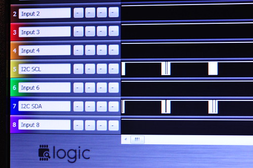
The Logic has a pretty easy-to-use bit of front-end software to handle all the set-up and UI work for the teeny-tiny hardware. It’s a UI that is unlike what you might expect from a bit of Windows-based software. It’s very gooey, using some subtle screen effects and UI elements that, for this OSX guy, are not what I think of when I think of XP. Which is good. It makes using the UI not feel like I’m being forced to drink a Rusty Nail or something for breakfast.
The analyzer samples much quicker than I normally have need for and does so without any problems. I’m usually down in the low range — .2 MHz and 1 M samples is usually plenty for what I’m doing. But, if you need a wider range of samples or a higher sample rate, the analyzer will go all the way up to 24 MHz. Those 9 conductors are 8 data lines plus one ground, so you can analyzer an 8-bit wide bus if you wanted at 24 MHz.
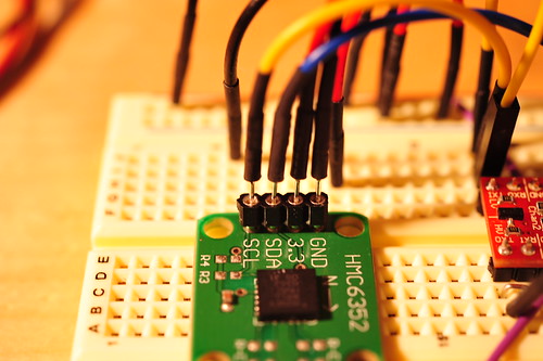
So, I put the Saleae Logic on the HMC6352 circuit to give it a shot. First, the HMC6352 set-up.
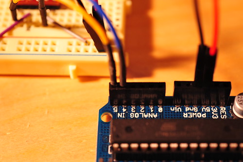
Although the HMC6352 has a wide voltage range, I was playing around with a level shifter circuit that was already hooked up to an Arduino on the bench, so I went ahead and just kept that circuit as is. So, the basic set-up is my Arduino I2C lines (SDA and SCL) going through a bi-directional level shifter shifts 3.3V 5V, and then to the HMC6352 SDA and SCL lines. I use yellow wire for SCL and blue wire for SDA.
I ended up using the Saleae Logic to dig a bit deeper into the communication between my microcontroller (an Atmega168 sitting on an Arduino) and the HMC6352 as a way to test out the logic analyzer.
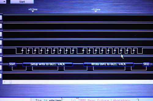
First I wanted to just probe the I2C communication. The basic transaction my Arduino code was doing was to send an “A” to the HMC6352. According to the specification sheet, writing an “A” to the device causes it to return two bytes of data — the high-order and low-order bytes of a 16 bit value indicating the compass’ heading. Easy enough. Here’s the Arduino doing just that. First, it sets up the write to the I2C device at address 0x21. Then it writes an “A” which, in the ASCII table, is the value 0x41. (N.B. The spec sheet says the HMC6352 is at address 0x42 but — and don’t ask me why — sometimes the address specified has to be right-shifted one bit in order to “take”. I mean I sort of know why, but I don’t know why this is the case sometimes — a r/w bit thing or something. Too much to bother with, but a good way to make good use of a logic analyzer when you’re stuck wondering why your device doesn’t seem to be listening to you. I learned this the long way and only had a fancy DSO to try and debug it.)
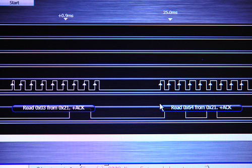
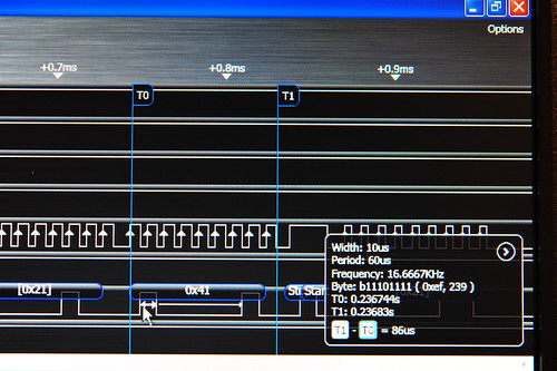
There it is in the top picture. A simple write to the device at address 0x21 with all the ACKs, meaning whatever is out there, heard us and is acknowledging receipt of the write. And, it looks like we get two bytes of data back — a 0x03 and a 0x64. The first byte will be the high-order byte and the second byte is the low-order byte. 0x0364 is 868, which we normalize by dividing by 10, to get 86.8 degrees. Done. I’m pretty sure that’s that. Finally, the measurement features are pretty cool — useful for confirming clock speeds or verifying a bit train. There’s a good use of a simple, pretty inexpensive ($150) logic analyzer that’ll certainly save you $150 worth of your time many times over. Plus, the small size and convenience of USB make it easy enough to fit on your bench and store away or travel around with when it’s not in use. My only quibble is that it’s only for Windows, but that’s a minor one. I don’t really play too hard in the OS religious wars. I run whatever makes my life easier at whatever moment. So, a $200-ish Windows chassis in the laboratory that just runs a few apps like some CAD software and things like my Propeller coding environment, .NET development, software for test equipment like this and AVR Studio 4 — it just helps me get things done rather than being adamantine about which OS religion I’ll adhere to and, then, not getting anything done except spending time porting things from one OS to another or complaining about how much a Windows license costs or whatever.
Wow. Okay. Off my high horse. Check this logic analyzer out. I can recommend it after using it for a few months.
#include

// http://wiring.org.co/reference/libraries/Wire/index.html
// On the Arduino board, Analog In 4 is SDA, Analog In 5 is SCL
// The Wire class handles the TWI transactions, abstracting the nitty-gritty to make
// prototyping easy.
// This sketch has a HMC6352 attached to the I2C bus, through a bi-directional
// level-shifter circuit.
int address = 0x42 >> 1;
 int reading;
void setup()
{

  Serial.begin(9600);

  CLKPR = (1<<clkpce);
  CLKPR = 0;

  // initialize the TWI / I2C Bus
  Wire.begin(); // join i2c bus (address optional for master)

}

void loop() {

  Wire.beginTransmission(address);
  Wire.send('A');
  Wire.endTransmission();
  //delay(10);
  Wire.requestFrom(address, 2);

   if(2 <= Wire.available())    // if two bytes were received
  {
    reading = Wire.receive();  // receive high byte (overwrites previous reading)
    reading = reading << 8;    // shift high byte to be high 8 bits
    reading += Wire.receive(); // receive low byte as lower 8 bits
    reading /= 10;
    Serial.println(reading);   // print the reading
  }

//  delay(50);
}
