Autonomous Game Controllers

JCB_01012009__142528_4160_DRV001

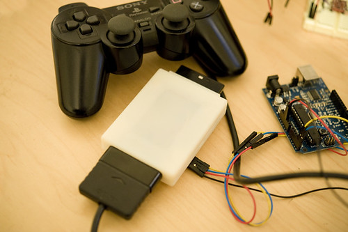
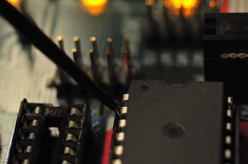
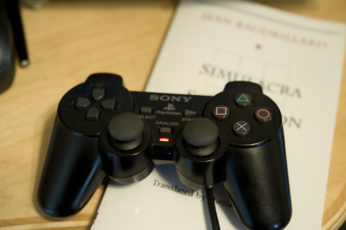
Continuing on my strange pursuit of designing weird interfaces that disrupt conventional game interaction rituals, I put together a bit more of my “PSX” project. You probably don’t recall, but this is the project where I’ve created a little “dongle” that can fool a PS2 (or Playstation 3, as it turns out..) into thinking that the dongle is actually a Playstation controller. You can also hook up a real Playstation controller to it and it can “read” the controller buttons and joystick and pass that data through, or do whatever you want with it. It appears as an TWI/I2C device to anything that talks to TWI/I2C devices..like my favorite TWI/I2C talking thing — the Arduino.

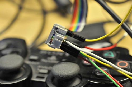
You can see here that the dongle — the white box with those annoying, huge Playstation connectors on either end, one male, one female — has four wires going into it. Those are for power, ground and the TWI signals, SDA and SCL. The power and ground are necessary because the Arduino (at least this one here) and the dongle run at different voltages. The Arduino is a 5V device, while the dongle is a 3.3V device, so there’s some level shifting going on inside there.

JCB_03012009__195744_4176_DRV001

190808_200037

So, that’s all fine. It works, etc. But then the question that’s actually more intriguing than building the thing..what do you do with it?

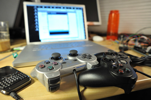
Well, I have some ideas, including hooking up a bike to it and attaching a giant human form kick-boxing dummy to play old school fighting games. For some early fun and nonsense, I connected a Wii Nunchuck up to it to control Playstation games with Wii-y gestures and stuff. Which could be cool if I find the right game, or spend a little more time thinking things through rather than just writing and revising microcontroller firmware to make a TWI controllable device, and doing Catia to CAD-up and print plastic enclosures.

But, in the meantime, I decided to do an absolutely crucial bit of game science. Something that I am entirely sure is mulled over constantly, but never properly investigated. The question is best stated thusly: how long would it take the Little Prince to roll up an entire room based on a random path algorithm?

How long indeed. Well, short answer is a long time. I let it go for about 70 minutes, after which he had just 10 things to go in a particularly tricky location that required rolling across a narrow bridge. At this point, I took over..but check out the 8x speed video anyway!

Katamari Autonomy from Julian Bleecker on Vimeo

I wrote a quick little Arduino code for my PSX dongle to have the Little Prince roll forward and then, after a few moments, make a random directional change. (Or stop, take a load off and look around the world.)

This was all done by sending TWI commands to the appropriate registers in my little DIY Playstation 2 controller emulator. All the buttons and the joysticks can be emulated as to their state through a series of write-to registers. If there’s a controller stuck in the other side of the dongle, there are a complement of read-from registers so you can see if any of the buttons are pressed and how much the joysticks are displaced. (I set up an “escape” buttons sequence — pressing both L2 and R2 — to bring control back to the normal joystick so I could navigate menus or take control over, which I had to do after I realized, with four items left, the completion of cleaning the room would probably not happen before the universe ran out of steam.)

Here’s the Arduino code. Pretty straight forward Wire / TWI library stuff.


#include
#include "nunchuck_funcs.h"

#define is_bit_clear(a, n) (0 == (a & (1<<n)))
#define is_bit_set(a, n)  (1 == (a & (1<<n))

#define is_button_pressed(a, button) is_bit_clear(a, button)
#define is_button_released(a, button) is_bit_set(a, button)

#define BTN_SELECT 0
#define BTN_L3 1
#define BTN_R3 2
#define BTN_START 3
#define BTN_UP 4
#define BTN_RIGHT 5
#define BTN_DOWN 6
#define BTN_LEFT 7
#define BTN_L2 8
#define BTN_R2 9
#define BTN_L1 10
#define BTN_R1 11
#define BTN_TRIANGLE 12
#define BTN_CIRCLE 13
#define BTN_X 14
#define BTN_SQUARE 15

// register addresses in the PSX I2C device
#define W_BUTTONS_0 0x00 // (, ^, start, R3, L3, select
#define W_BUTTONS_1 0x01 // (square, x, o, triangle, R1, L1, R2, L2)
#define W_RIGHT_X 0x02
#define W_RIGHT_Y 0x03
#define W_LEFT_X 0x04
#define W_LEFT_Y 0x05

#define R_BUTTONS_0 0x12 // (, ^, start, R3, L3, select)
#define R_BUTTONS_1 0x13 // (square, x, o, triangle, R1, L1, R2, L2)
#define R_RIGHT_X 0x14 // a value from 0x00 - 0xFF
#define R_RIGHT_Y 0x15 // a value from 0x00 - 0xFF
#define R_LEFT_X 0x16
#define R_LEFT_Y 0x17

// I2C address of the PSX dongle
int psx_dongle_addr = 0x72;
int j;
void setup()
{
  Serial.begin(9600);
  randomSeed(analogRead(0));
  Wire.begin(); // join i2c bus (address optional for master)


// this is the control register. setting it to 1 means that
// we have to tell the PSX device what data to send to the
// Playstation2. Setting it to 0 means that it simply passes
// through the data from the controller to the PS2. We can
// read the state of the contorller at any time.

writeToAddress(psx_dongle_addr, 0x24, 1);
}

// we'll use count to figure out when to change direction
int count = 0;
int buttons;

// mode is used to indicate either "pass thru" where we can use the
// actually real human controller to control the PS2, or to generate
// data via the PSX dongle.
// pressing both L2 and R2 simultaneously toggles the mode
int mode = 1;
byte randomNumber;

void loop()
{
  byte val;
  count++;
  //Serial.println(count, DEC);
 // 0x70 shows up as either ID $20 or ID $E0 on Propeller

/*******************************************/
/*
  BTN_SELECT = $0001
  BTN_L3 = $0002
  BTN_R3 = $0004
  BTN_START = $0008
  BTN_UP = $0010
  BTN_RIGHT = $0020
  BTN_DOWN = $0040
  BTN_LEFT = $0080
  BTN_L2 = $0100
  BTN_R2 = $0200
  BTN_L1 = $0400
  BTN_R1 = $0800
  BTN_TRIANGLE = $1000
  BTN_CIRCLE = $2000
  BTN_X = $4000
  BTN_SQUARE = $8000
**/


// 0x00 write to BUTTONS_0, 0x12 read from BUTTONS_0
// 0x01 write to BUTTONS_1, 0x13 read from BUTTONS_1
// 0x02 write to RIGHT_X, 0x14 read from RIGHT_X
// 0x03 write to RIGHT_Y, 0x15 read from RIGHT_Y
// 0x04 write to LEFT_X, 0x16 read from LEFT_X
// 0x05 write to LEFT_Y, 0x17 read from LEFT_Y
//Serial.println(getButtons(), HEX);
//int buttons = getButtons();
//Serial.print(buttons, BIN);
//  passThruButtons();

if(count > 512) {
  count = 0;
}
//Serial.println(mode, HEX);

// get the buttons
buttons = getButtons();

// mode is used to indicate either "pass thru" where we can use the
// actually real human controller to control the PS2, or to generate
// data via the PSX dongle.
// pressing both L2 and R2 simultaneously toggles the mode
  if(mode == 1 &&
     is_button_pressed(buttons, BTN_L2) && is_button_pressed(buttons, BTN_R2)) {
    mode = 0;
    delay(1000);
  } else
  if(mode == 0 &&
     is_button_pressed(buttons, BTN_L2) && is_button_pressed(buttons, BTN_R2)) {
     mode = 1;
     delay(1000);
     }
 if(mode == 1) {
passThruAllAndShow();
 }
 if(mode == 0)
  {

  writeToAddress(psx_dongle_addr, W_LEFT_Y, 0x00);
  writeToAddress(psx_dongle_addr, W_RIGHT_Y, 0x00);
  passThruButtons();

  if(count == 512) {
    count = 0;

    randomNumber = random(1,5);
        Serial.print("FLIP! ");
        Serial.println(randomNumber, HEX);
    switch(randomNumber) {
      case 1: case 2: case 6:
        writeToAddress(psx_dongle_addr, W_LEFT_Y, 0x00);
        writeToAddress(psx_dongle_addr, W_RIGHT_Y, 0xAF);
        delay(500);
        break;
      case 3: case 4: case 5:
        writeToAddress(psx_dongle_addr, W_LEFT_Y, 0xAF);
        writeToAddress(psx_dongle_addr, W_RIGHT_Y, 0x00);
        delay(500);
        break;
          default:
         delay(500);
         break;
    }
  }

  /*
writeToAddress(psx_dongle_addr, W_LEFT_X, (float)map(nunchuck_accelx(), (float)0x48, (float)0xB0,
                (float)0x00, (float)0xFF));
writeToAddress(pssx_dongle_addr, W_LEFT_Y, (float)map(nunchuck_accely(), (float)0x48, (float)0xB0,
                (float)0x00, (float)0xFF));

writeToAddress(psx_dongle_addr, W_RIGHT_Y, (float)map(nunchuck_joyy(), (float)0x1D, (float)0xDF,
                (float)0x00, (float)0xFF));
writeToAddress(psx_dongle_addr, W_RIGHT_X, (float)map(nunchuck_joyx(), (float)0x1D, (float)0xDF,
                (float)0x00, (float)0xFF));
*/
}

delay(10);
}


//
int getButtons()
{
int result = 0x00;

result = readFromAddress(psx_dongle_addr, 0x13, 1);
//  Serial.print(result, HEX); Serial.print(" ");
result <> 8)); // MSB
  Wire.send((int)(addr & 0xFF)); // LSB
  Wire.send(data);
  Wire.endTransmission();
}

byte readFromAddress(int twi_addr, int addr, int bytes_to_read)
{
  byte rdata;
 Wire.beginTransmission(twi_addr);
  Wire.send((int)(addr >> 8)); // MSB
  Wire.send((int)(addr & 0xFF)); // LSB
  Wire.endTransmission();
  Wire.requestFrom(twi_addr,bytes_to_read);
  while (Wire.available()) rdata = Wire.receive();
  return rdata;
}
Continue reading Autonomous Game Controllers

Timing

Next step, testing the PCB edition of the PSX. I’m back to using a slow, low STK500 to do some debugging. Now that the firmware is fairly well squared away, most of the debugging is either a poorly solder-pasted pin (knock-wood).

I did find a curious little 30 minute bugaboo today. While I was making sure that data was being read properly from a controller by itself, I noticed that bits were being consistently dropped. It looked as though things like button presses on the controller were toggling two bits instead of one, and, for example, the first byte that indicates button presses for things like Start, Select and the direction buttons, was always missing the least-significant bit.

It turns out that the way I am emulating requests and data transfers to the controller is particularly sensitive to timing. I’m not 100% sure what the deal is, but the controller I had been using a few days ago was okay with an 16uS clock period. Now, these two I had lying about the studio weren’t working so great with that period — when I changed the clock to a 40uS period, things clicked back into shape.

(I’m sort of wondering whether the series resistors for the firmware generated clock I’m using is too high — I ended up putting a 1.8k resistor rather than the 1k resistor I have in the breadboard prototype, just cause that’s what I had handy.)

In any case that problem got me to thinking that, as other folks have mentioned, the controllers are sensitive to timing — I may need to add one additional control register to the set up so that this timing value can be adjusted easily, rather than sticking it as a constant in the firmware.
Continue reading Timing

Refining

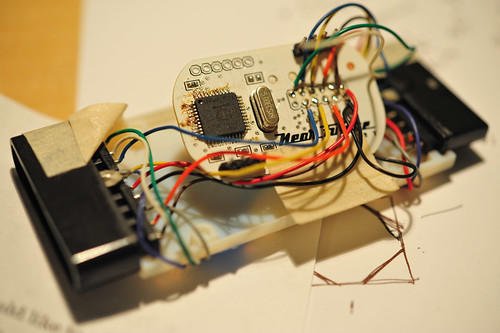
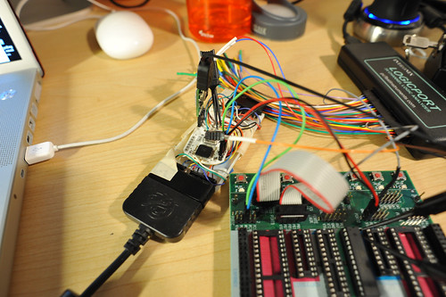
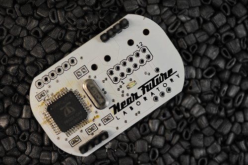
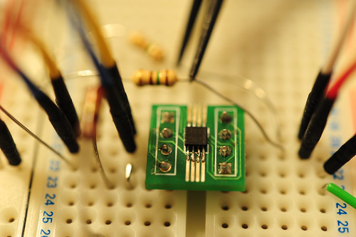
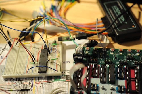
I’m getting closer to have a second prototype of the PSX project. Strangely, I seem to be building the breadboard prototype (lower image) simultaneous with the PCB prototype (the thing on top). I think the breadboard prototype is mostly for working on the firmware for the Propeller, which is going better than I had hoped, especially seeing as I’ve never developed for it, and that I’m mostly in Spin assembly (not so ugly, but still..bleech..) The breadboard version is basically a core Propeller with some wiring for programming and for chatting to an EEPROM for permanent firmware storage. I started playing with this PCA9306 bidirectional level-shifter, which is sitting on the right half breadboard. This is basically the same circuit as what goes on the surface mount PCB, except for the addition of a LP2985 3.3v regulator.

This is a curious approach, getting slightly ahead of things, but it’s been a circuitous, round-about project from the original “hey..wouldn’t it be cool if..?” motivation that I thought would maybe be a weekend’s work of getting an Atmega324 to emulate a PSX controller. That’s the one in the image above, from last fall. I began the design last summer thinking I’d be done in short order. It should be..I’ve just got grease in my head or something. I was anticipating perhaps some trickiness because I took the trouble to pull out the boundary scan signals to the edge of the board so I could do some JTAG debugging. What went wrong? Well, mostly timing related things. This project motivated me to get my own logic analyzer so I could figure out what the heck was going wrong. There were mostly timing-related problems that I sort of pushed to the side to pursue another possible solution, which led to this current (v07) design.

How did this all start? I thought it’d be an interesting little bit of game controller provocation to have a controller that “got tired” just as one’s avatar might in a video game. To do this, I figured I’d have to Continue reading Refining

PCA9306 Level Shifter

Persistent nagging problem — shifting logic levels between devices that are fabbed with different technologies so their voltages end up being different. Digital circuits “trigger” based on voltage levels — a logic 1 or high signal is relative to the electrical specifications of the device and the fabrication process of the silicon. (A techie diagram is available here.) It’s not a new problem, but one I seem to be coming across more and more as I use the Arduino to do quick sketches of project ideas, or to stand-in for a more embedded solution that might use another of the Atmel 8-bit devices later on when the design and details are more refined.

I’ve tried a bunch of things, including the kind of canonical reference circuit from Philips that uses the BSN20 MOSFET. Sparkfun has a neat little breakout board using a MOSFET, the BSS138. Same principle, built out for you by the fine folk at Sparkfun.

While poking around some more what cause of this PSX project where I have an Arduino trying to talk to a Parallax Propeller, I found reference to a single-chip solution from TI that’s called a PCA9306, which is that small guy up in the photos above. (Just a hair smaller than an 8-pin SSOP package, which means that it was too small to fit on this SSOP break-out — the pins don’t reach the copper, so I had Igor do some hand work to get that to take hold.
Continue reading PCA9306 Level Shifter

Propeller and Arduino

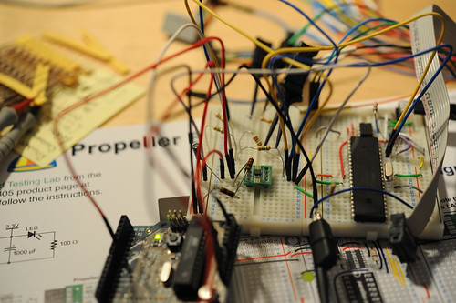
Not the most exciting thing, but an interesting challenge here. I’m trying to get a Parallax Propeller chip to behave nicely as an TWI/I2C slave with the idea that I’d like to create a pretty much black-box interface that’ll allow a TWI/I2C master to control it for stuff. Ultimately I’d like to use the Propeller in the PSX project. It’ll sit in between a Playstation 2 and a normal Playstation controller, and be available as a TWI/I2C slave, so that another device, that doesn’t really care to figure out how to talk to a Playstation 2 or its controllers can make the PSX box with the Propeller in it emulate, for the Playstation, certain button presses, etc. Or, it could “read” over TWI/I2C from the PSX box and find out what the real controller is doing. Or, it could just read or write from a special TWI register address to make the PSX box (with the Propeller in it) just do a “pass-thru” so that the signals just go straight through as if there were nothing in between.

That’s the theory. In practice, setting up this test jig took more time that I would’ve thought.
Continue reading Propeller and Arduino

PSX (With Propeller) — Digital Edition

DSC_5329

So, feels just a little bit like converting religions or something, but I’ve started looking into other kinds of microcontrollers for practical reasons as well as to just generally expand what sits in my prototyping sketchpad. I’ve been curious about the Parallax Propeller, which has a multi-processor (they call them “Cogs”) core and can do video and audio gymnastics. It uses its own proprietary language called “Spin” which is pretty legible if you’ve done any high level programming. Assembly is also an option. The idea of having a small “microcontroller” that has built in multi-processor capabilities feels a bit over-blown, but it’s actually fairly liberating in the design phase. Suddenly, projects start to look like parallel tasks that can be designed with object-oriented sensibilities in mind. All of the “task switching” (cog switching) is handled automatically. Timing and so forth is fairly static so it’s possible to predict precisely how often tasks will get run. The Propeller will also run wickedly fast — way faster than an Atmel 8-bit microcontroller. Normally, speed hasn’t been an issue for projects, but it’s nice to have some overhead — up to 80 MHz in this case (versus 20 MHz for the Atmel, which is more then enough for most things, but the lickity-split clock makes doing embedded video projects possible.

Anyway, this seemed like a good possible fit for the PSX project because I need to simultaneously read a joystick and service polling requests from the console. I probably _could_ do both of these tasks with an Atmel microcontroller running at 20 MHz, interrogating the controller in between the console’s polling. Experience thus far has led me to think that this may not be the easiest thing to do, even sequentially. I’ve tried just servicing the console using the built-in SPI hardware in an Atmel 8-bit microcontroller and the timing is a bit flakey. Perhaps someone with a little more expertise in these things could take this on.

[ad#ad-1]

In the meantime, I went for a few extra cylinders and some more octane, which works better than well-enough.

I found some code that Micah Dowty put together for a Playstation project called Unicone. He had some code there in the midst of that project that was easily adapted to my weird PSX controller-that-gets-tired project.. Works like a charm.

I can specify the data that’ll go across the wire very simply, as a pointer to a buffer of data and Dowty’s object takes care of all the rough-stuff communication to the console. I can even specify what kind of controller I’m emulating, if I want. What’s left is to create an object that polls the real controller, makes some decisions about how “tired” it should be and changes the analog control stick values based on that tiredness and places this data in the buffer. Because the Propeller’s “Cogs” can share data, this should be pretty easy..

This is a trace of communication when I use the code below. The buffer is sent across just as it is, and Dowty’s object is smart enough to send it as if it were a simple PSX analog joystick N.B. the first two bytes after 0xFF, 0x73, 0x5A pre-amble are the button settings, as a 16 bit word, followed by four bytes representing the analog joystick positions. In the DAT section of the code at the very bottom of the listing below, this is exactly what I want sent. Simple.

PSX..Analog Edition

20080707_02-57-53

So, this is my analog version of a playful Playstation 2 controller for the PSX project — the one that slows the analog part of the controller down over time so, you know..when I’m playing Katamari Damacy it’s a bit more realistic that the Prince gets tired or during GTA, my guy actually gets tired from running away from liquor store heists and stuff.

I’m looking at two approaches. The first is digital — basically intercepting and modifying the communication between the console and the controller. (I’ve described the protocol, and there’s lots of great, hard-gained information out and about describing how it works.)

It’s a good, playful idea as a kind of theory object, entirely doable, kinda complicated and perhaps a bit of an over-designed solution for a simple idea. What I want is something made (constructed, 3D-printed, wired-up, soldered, fab’d, modeled, fussed-over, troubled-with, a cause of grief, etc.) rather than only just discussed. More than discussing only with words (still the greatest instruments for making things) the object also explicates the tension between physical-digital worlds, or the “real world” and “second life”.

This isn’t something that’s a mass-market product design concept, which should be pretty obvious. (Why is it always assumed that productions from the laboratory are products rather than conversation pieces? I would rather make objects that enter into conversations with a provocation, or enter into discussions, raise questions, help create disruptions by describing new interaction rituals, not making least-common denominator products. These are objects that speak — they create, perpetuate and incite discussions — even inspire new concepts that link 1st life with 2nd life, such as “feeding” characters in games in some fashion, which is closer to the motivation than simply trying to hobble a game character. It’s a theory object. The “theory” embodied in the PSX controller concept here is meant to disrupt the conventional understanding of the relationship between physical activity in 1st Life and virtual-physical-digital activity in 2nd Life digital worlds.)

20080707_02-57-20

This is the second, more expeditious design. Basically, I tap right into the PSX controller, putting a microcontroller in between the analog control joysticks and the little FPGA or whatever it is that senses the analog control joysticks. So, my microcontroller determines where the control sticks are and, depending on how long the game’s been played, “dampens” the value, constraining its range.

[ad#ad-4]

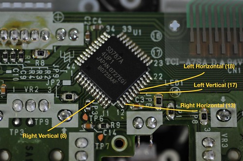
It’s a simple “tap” in between, which requires a bit of less-than-elegant de-soldering and pad lifting (or trace cutting) in order to create the cut-in point for the hardware that’ll sense and then spoof the console.

In this case, for testing I used an Arduino, which has enough built-in analog-to-digital converters to sense the positions of the four potentiometers (right-horizontal, right-vertical, left-horizontal, left-vertical) that make up the two joysticks. It also has an I2C/TWI/2-Wire interface that I can use to control four digital potentiometers. The digital potentiometers will appear to be the normal joystick potentiometers only with their values slightly clamped over time to dampen the effects of your normal input.

20080707_04-52-02

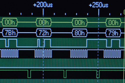
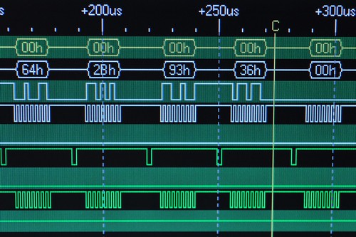
The joystick potentiometers produce 8-bit values in the interface protocol, and are around 0x80 (or so..) in the middle, when they haven’t been displaced. Here’s a snip from the larger interface protocol showing, from left to right and in the white trace, right-horizontal, right-vertical, left-horizontal, left-vertical. Each value is in the middle range meaning that the joysticks aren’t displaced. If, for example, the right vertical joystick was fully displaced upward, the second value would be 0x00 (full down would be 0xFF.)

I wrote a simple little Arduino sketch below that does a 10-bit analog-to-digital conversion of the right and left vertical potentiometers. Because the PSX controller seems to have a limited, 8-bit range, it’s necessary to dampen the 10-bit value. Just through experimenting, I found that dividing the 10-bit A2D value by 6 (sort of like right-shifting 2 1/2 times), I could get pretty close to what the controller was producing in terms of a range of values. (I don’t quite get to 0, but it’s close enough.)

I then test attenuating the range by using a constraint function built into the Arduino extended library. This function “clamps” the range of a value passed into it, so I can (in another version) gradually constrain the range that the potentiometer can go through.

Effectively, for this example, when either joystick is full up, the range of the digital potentiometer is clamped, so that the value that the controller senses is not quite a full displacement, no matter how far the player pushes it up. (The same works for downward displacement.) In this case, full upward displacement clamps the right vertical to 0x2B (second from left) and the left vertical to 0x36 (fourth from left). (You can see that the horizontal displacements are off-center because the joystick has been moved and isn’t dead-center in the horizontal direction.)

20080707_04-52-39

20080707_04-47-53

//
// Control the Playstation console
// by spoofing the PSX controller

#include
int RY_Pot = 0;
int LY_Pot = 1;

void setup()
{
  Wire.begin();
  analogReference(EXTERNAL);
  Serial.begin(9600);
}

int val = 0;
int bias = 0;

void loop()
{

  // bias runs between about 23 -90 -  155
 // read the value from the right vertical joystick
  val = analogRead(RY_Pot);

 // transmit to device 0x28
 // which is a DS1803 digital potentiometer
  Wire.beginTransmission(0x28);
// prepare to write to potentiometer-1
  Wire.send(0xAA);
  bias = val/6;
 // Serial.print("RX ");
 // Serial.print(val, DEC);
 // Serial.print(" "); Serial.println(bias, DEC);
 // a bit of fudge..
  if(bias < 30) bias -= 10;
  // sends potentiometer-1 value byte
  Wire.send(constrain(bias+15, 60, 120));
  Wire.endTransmission();

 // do the same thing, for the
 // left vertical joystick
  val = analogRead(LY_Pot);

  Wire.beginTransmission(0x29);
  Wire.send(0xA9);
  bias = val/6;
// Serial.print("RY ");
// Serial.print(val, DEC);
// Serial.print(" ");
// Serial.println(bias, DEC);
  if(bias < 30) bias -= 10;
 // sends potentiometer value byte
  Wire.send(constrain(bias+15, 60, 120));
  Wire.endTransmission();     // stop transmitting

  //delay(100);
}
Logicport Overview

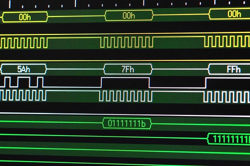
So, just a brief overview here of the Logicport Logic Analyzer and it’s top-line features and set-up. When I set out to figure this thing out, I took a decent “known” set-up that was running a not terribly complicated, but still useful protocol — SPI. As it happens, the Playstation 2 communication between its controller is roughly the SPI protocol, so that’s as good a test as any, seeing as I had been doing some work with the PS2 anyway.

I wrote a bit about that set up already, so this is the part where I describe how I set the Logicport up. Here are links to two other posts related to the Logicport.

PS2 Logic Analysis
Logic Analyzer

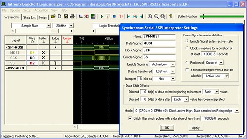
There are three main features of the Logicport I’ll describe — Interpreter’s, Triggers and Measurements. (I’ll also briefly describe some of the basic set-up things that I learned.) Interpreters are like templates for specific protocols. The Logicport supports four protocols as these Interpreter “templates — I2C/TWI, SPI, RS232 and CAN 2.0A/2.0B. For the work done at the Near Future Laboratory, we’re basically covered with these.

Creating a new Interpreter from one of these templates is pretty easy. Just with the case of a SPI Interpreter, your job is to specify which of the Logicport’s channels is probing which of the standard SPI channels. In my setup, I configured two different Interpreters — one for the “master” side and one for the “slave” side. On the master side, the Interpreter probes for the MOSI (master-out, slave-in), SCK (serial clock) and SS (slave select — active low) channels. The “slave” side the Interpreter probes for the same stuff, except the data moves across the MISO (master-in, slave-out) channel.

The Interpreter configuration window also allows you to specify a whole bunch of other useful things. First off is the bit order. The PS2 SPI style protocol sends data least-significant bit first, which is okay, but opposite of the canonical SPI protocol. Fortunately, the Interpreter allows you to specify this. You can also tell it how many bits to interpret as data, and what format you want that data to be represented — Hex, Binary, Decimal, Signed or ASCII. So, that’s super useful.

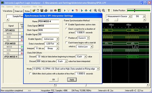
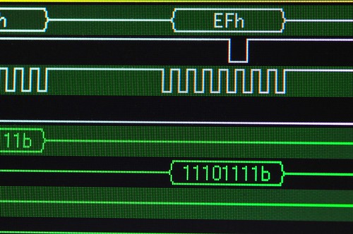
In the lower image above (click it to enlarge it if you need), I’ve set up this additional slave Interpreter, called PSX-MISO-4, to take advantage of a few additional features of the Interpreter. What I wanted to do was isolate the 5th byte of slave data. So, the fifth chunk of information sent by the slave across the MISO channel. In the PS2-controller communication, this represents the right bank of buttons on the controller — triangle, square, circle, ex — as well as the front triggers — L1, L2, R1, R2. (Here’s more information about the frames of data and what they represent.) So, simply for convenience and to make things easy to interpret, I can specify that this particular Interpreter ignore the first 32 bits of data — four bytes — and just start interpreting and showing the data afterwards. Because I _really_ want to isolate this one byte alone, I also tell it to ignore basically everything else after it does the interpretation of the fifth byte — so I just say, ignore the next 800 bits.

[ad#ad-4]

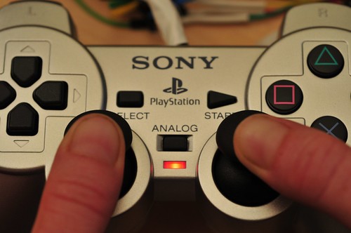
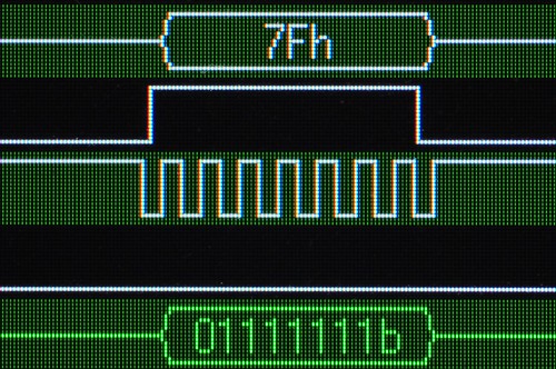
And, you can see in that second image above, that that one byte is represented in binary, which is useful because each of those switches can be interpreted as a 1 (switch open) or a 0 (switch closed or pressed) without converting from decimal or hexadecimal. Here I’m holding down the triangle and ex buttons simultaneously, so bits one and three are 0.

You can also see that the SPI Interpreter allows you to specify the SPI “mode” — clock phase and clock polarity. This can be useful for trying to figure out how an unknown part is actually operating. In my experience, this can be one of the two or three serious “gotchas” when debugging SPI.

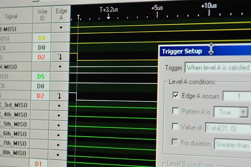
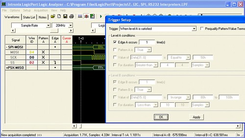
Triggers are probably the first thing you’ll set up, but I guess the second thing I’m describing, partially because I haven’t had any complicated triggering scenarios. In the case of the SPI protocol, you want to trigger when the SS line goes low, or active. This is basically saying that the master is beginning to communicate with the slave, which is usually where your interest starts. And this is what this particular Trigger configuration specifies — Trigger when Edge A occurs once. In the main Logicport window, I specify Edge A as a falling signal on the SS line. Easy-peasy. More complicated triggers could be specified, including the variations you can see greyed out in the configuration window. If you had lots of parallel data from a data bus or something you could specify a specific data value, for example. (One thing that would be nice would be to trigger on a specific SPI MOSI value or a specific I2C device address but for reasons I don’t entirely understand, it was explained to me that this is the equivalent of time travel or something. The work-around is to create a debug trigger on an unused signal from your device to indicate that the thing you want to start watching is now happening and use that signal to trigger the Logicport. Fair enough.)

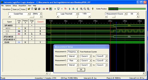
Finally, Measurements. Another very useful and very configurable-y feature. Measurements use either a set of six movable “cursors”, the trigger point or a specific channel to make time-based measurements. You use this Measurement window to specify what you’d like to measure and what you will use to make that measurement. Here I’m using all of them. First, Measurement A is a frequency measurement, using the built-in Hardware Counter (nice..). With this kind of measurement, I have to specify the source, but not in the Measurement Setup window, strangely enough. In the top of the main window, I specify the Measurement A Source as channel D6, which is the blue/white wire from the Logicport. In this case I have clipped that wire to the clock out (CLKO, PB1) of the Atmega324 that’s sitting on my STK500 break-out board. This simply routes the clock signal that the Atmega324 is using to that specific pin. I’ve got a 16MHz crystal connected to the XTAL pins, and so I see a roughly 16,000,000 Hz frequency measurement for Measurement A, as shown in the bottom part of the main window.

Measurement B is a time interval between Cursor A and Cursor B. That’s basically the clock period of the SCK, the SPI clock, which comes out to be 2uS. Measurement C is the same thing, only the frequency of the SPI clock, or 500KHz. Finally Measurement D is the time between Cursor C and Cursor A, which is the time between SS going low and the first bit of MOSI data, 20.1uS. (I could have also specified “Trigger” instead of Cursor C, which might’ve been more accurate.)

These are the main Logicport features I’ve used to get a basic understanding of how it works. It’s pretty straightforward, particularly for simple set ups like this. The other configurations I’ve had to tweak in order to get good analysis has been the sample rate and the logic levels. I’ve had to vary the sample rate, especially when putting a microcontroller on here that’s faster than the sample rate. With the PS2 on its own, and if I’m not measuring signals from a faster microcontroller, I can slow the sample rate down to 1 or 5 MHz. (Not that it matters a whole lot, unless I want to acquire more total samples.) The logic level specifies what counts as logic high (1) and logic low (0) for the logic analyzer. If you specify it too high, your data will go away, or appear flakey, mostly because the logic analyzer is starting to interpret noise or other spurious signals. And, speaking of noise, the Logicport has four wires that are grey wires with black heat shrink. These are for grounding the device to other things, which is crucial to avoid noise. In the case of my setup, I have one grounding the PS2 and another grounding the STK500 breakout board. This creates a common ground across all three boxes and basically eliminates spurious data and other signaling weirdness.

Playstation 2 Logic Analysis

Back for a bit to the world of prototyping peculiar Near Future kinds of things. I’m still working through this anti-game controller, game controller to do some experiments in alternative sorts of mobile interfaces for traditional game devices.

First, there are two other posts on the Logicport and related stuff, and I’ll just flag them here:

Logicport and I2C
Logicport Overview

I did some quick experiments with the Logicport to get my head around its operating features. (My previous brief analysis is here.) I was mostly motivated to work with a logic analyzer because many of the prototyping sketches I do require some sort of communication between devices using protocols like I2C/TWI, SPI or standard serial communication. If you can get these protocols to work right the first time, then you’re golden. Sometimes though, something goes wrong and debugging can be a pain. I’m the kind of guy who likes to see what’s going on rather than guess, and tools like a digital scope and logic analyzer are indispensable for me. It’s just a preference I have to invest in some pro gear, within a reasonable budget. Seeing as I was trying to get this PSX project done and had trouble debugging it, I figured this was as good a reason as any to go ahead and get it and figure out how to use it.

The Logicport is pretty reasonable for a 34 channel (plus 2 dedicated clock channels) logic analyzer because it offloads a lot of the heavy lifting to your PC — $389 with everything you need except the computer. I told myself I’d get one when I had some trouble debugging what should’ve been a fairly straightforward interface — hooking up a microcontroller to a Playstation 2 to make the PS2 think the microcontroller was the normal Playstation controller. This got a bit tricky to debug with just a digital scope that had only two channels with which to analyze essentially a protocol that was using five channels.

[ad#ad-4]

The Playstation 2 interfaces to its controllers using a protocol that is basically SPI (Serial Peripheral Interface). The protocol for SPI is fairly straightforward. There’s a clock (SCK) to synchronize bits of data across two channels: Master Out, Slave In (MOSI); Master In, Slave Out (MISO). MOSI bits are data moving from the master device to a slave device. MISO bits are data moving from the slave out to the master. It’s like a two lane highway of data, with each data bit synchronized by the clock. Additionally, there’s a “slave select” (SS) channel — one per slave device — that tells the slave whether or not it is “active” and should listen to data bits coming across the MOSI channel, or send data bits across the MISO channel. (Reasonably, only one slave device should be active at a time.)

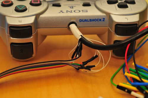
So, that’s four channels. The Playstation 2 actually uses this plus an additional line that is not specifically part of the SPI protocol — an “Acknowledge” (ACK) line. This is used to “acknowledge” to the Playstation 2 console each “frame” of data. That’s just the way it works, and the one feature that is a bit outside of the SPI protocol. (I fabbed-up a simple splice along the Playstation 2 controller cable to watch the protocol and try and figure it out. The splice has a simple IDC-style connector that I can use to plug into to either read the channels or, eventually, connect to a microcontroller.)

There are a few pages online describing the specifics of how a Playstation 2 controller works, including ways to interface the controller itself (the joystick) to microcontrollers.

What I’m trying to do is that, but a bit more, which is to interface a microcontroller that behaves like a Playstation 2 controller to the Playstation 2 console. To do this, the microcontroller needs to respond as a (kinda) SPI slave device, just as the Playstation 2 controller does.

To start this whole business, I tried first writing code “blind” — just looking at descriptions people had put up of how they did this, especially Marcus Post’s work, which has some PIC code to look through. I ported this as best as I could to the Atmel platform (running on a 16MHz Atmega168 on an Arduino), but was having some “hiccups” where quite often the Atmega168 seemed to loosethe protocol. Why? It was hard for me to figure out.

So, two things going on here. One — verify the console-to-controller protocol that the Playstation 2 uses. Two — figure out how to use the Logicport. I’m going to leave two for later, and first show the analyzer crunching on the PS2 console-to-controller communication.

Okay, first thing I did was connect up six of the Logicport’s 34 channels as if we’re analyzing a SPI protocol which, basically, we’re doing. We need MOSI, MISO, SCK (clock), SS (slave select), plus the ACK channel. We also need a ground line to have a common electrical reference. These signals are analogous to the one’s the PS2 uses, only with somewhat different names — they are CMD (MOSI), DATA (MISO), CLOCK (SCK), ATT (SS) and ACK in PS2 speak.

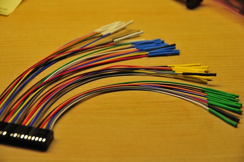
The Logicport breaks up its 34 channels into 4 groups of 9 channels (that’s 36, but two of them are dedicated clock channels), with each group color coded by a bit of heat shrink tubing on the end of a colored wire. This makes it easy to figure out which channel is being represented in the software display. (Here’s a plug module that pops into the Logicport. These are convenient cause you can have one semi-permanently connected to individual projects so you’re not always re-wiring. Just save the Logicport file for each project with the same channels and pop the plug module into the main Logicport box.)

So, I just took the “white” group and connected the MOSI, MISO, SCK, SS and ACK channels from the Playstation 2 “splice” cable. I used yellow for MOSI/CMD, black for SCK/CLOCK, red for SS/ATT, brown for ACK, and green for MISO/DATA. With these signals connected from my “splice” cable to the Logicport, I should be able to start seeing the acquisition. (I’ll go over setting up Triggers and Interpreters in a later post. For now, let’s just see what a little fussing gets us.)

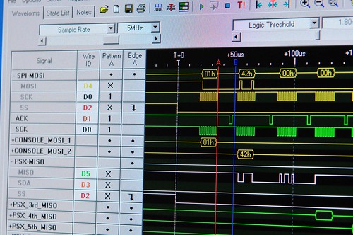
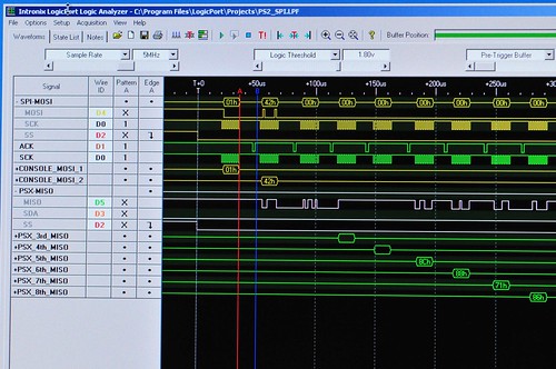
The Playstation 2 protocol is pretty straightforward. It starts out with the console activating the SS/slave-select line (channel D2, red/white) to indicate to the controller to start paying attention. SS is active low, so the channel drops from high to low to indicate “pay attention now.” Following this is a 0x01h byte of data along MOSI/CMD — channel D4, yellow/white. You can also see how the Interpreter can represent the data across a specific channel by aggregating bits and turning them into something useful, like a hex number. (You can also fold up these groups of channels if you don’t want to stare at individual bits.)

So, this is the basic preamble for communicating between the console and the controller. After the 0x01 the console sends the command 0x42, which basically means — send all your data. Simultaneously, the controller sends back a specific ID to indicate which type of controller it is. In this case, the controller ID is 0x79. Following this the controller sends a 0x5A to sort of say — data is coming.

The data that follows is basically the state of all the controller’s buttons and the analog controls’ positioning. For this controller, there are six subsequent bytes of data. For this particular controller, they’re like this (Here’s a more complete table for other kinds of controllers.):

Analogue Controller in Red Mode
BYTE    CMND    DATA
01     0x01   idle
02     0x42   0x79
03     idle    0x5A    Bit0 Bit1 Bit2 Bit3 Bit4 Bit5 Bit6 Bit7
04     idle    data    SLCT JOYR JOYL STRT UP   RGHT DOWN LEFT
05     idle    data    L2   R2   L1   R1   /   O    X    |_|
06     idle    data    Right Joy 0x00 = Left  0xFF = Right
07     idle    data    Right Joy 0x00 = Up    0xFF = Down
08     idle    data    Left Joy  0x00 = Left  0xFF = Right
09     idle    data    Left Joy  0x00 = Up    0xFF = Down

All Buttons active low.

For example, the acquisition image at top shows the “LEFT” arrow button being pushed down on the controller. Huh? Yeah, see — the right most bit in the white trace? It’s actually low — a little hard to tell cause of the angle, but it is. The PS2 spits out data least significant bit first, which means that bit 0 comes before (in time) bit 7, so the 0 at the end is bit 7, and bit 7 in byte 4 indicates whether the LEFT arrow is pressed, and everything is active low here, so a 0 means — pressed. (As I understand it the SPI protocol normally is the other way around, but luckily with the Logicport you can specific the bit ordering.)

Byte 5 is for the other buttons. This image shows bit 4 activated (low) indicating that the triangle button has been pressed. The bytes that follow are the the joysticks to indicate their positioning along their two (left/right, up/down) axes, running between 0x00 and 0xFF, with their “nominal” (centered) value being about 0x8C-ish, depending on how sticky they are and other things — they’re analog potentiometers which have a little bit of tolerance for variation for mechanical reasons and such.

Here’s an overall view of the entire transaction — the three bytes of preamble, followed by six bytes of controller state data starting around the 100uS. (Those bytes are near the bottom, staggered, in green. Next time I’ll explain how I set that view up.)

(Note that the acquisition shows that the console actually holds the SS/ATT signal for the equivalent of another six bytes of data. I’m not 100% sure why, but perhaps there could be additional data bytes for this sort of controller that I’m not getting. In any case, both the console and the controller send nothing back and forth. It’s just clocked nulls for another six bytes. So, off to the right of this image is lots of clock signals, and ACKS, but no meaningful data, until the SS pulls back high. Also notice the ACKS in the fifth channel (green) — these are acknowledge signals sent from the controller back to the console to verify that it’s alive and so forth. Evidently, these are necessary for the communication to work, but not strictly part of the SPI protocol. (Also, I am calling this SPI because it’s close enough, and provides a bit of a context for describing the communication and taking advantage of the Logicport’s SPI Interpreter. Technically I suppose it isn’t SPI.)

What’s next? Well, a brief overview of how I configured the Logicport to acquire the protocol data. And, now that I can actually see what’s happening and have a better understanding of the SPI-like console-to-controller communication, I should be all set to make a microcontroller behave like a Playstation 2 controller so I can spoof the PS2 and control it from other kinds of things.

[ad#ad-1]