Pretty Maps – 20×200 Editions

Some of you may have noticed, mostly probably not — but the Laboratory has expanded its ranks. It’s starting to feel like a proper design collective in here. One of the lovely attributes of the people in the Lab are the broad sectors of activity they cover that doesn’t make it seem like they do a zillion different things, but do many things to work though a relatively core set of interests.

Take Aaron Staup Cope. He writes algorithms that tell computers what to do. He makes maps out of paper. He makes maps out of algorithms. He makes you think about the ways that algorithms can do things evocative of map-ness..on paper.

Etc.

What I’ve learned from all of Aaron’s exploits in Dopplr-land, Open Street Maps-land, Walking Maps-land is that maps are dynamic, living things that should never be fixed in their format, style, purpose. They should never be taken for granted — even if the Google Map-ification of the world is doing just this. They should come in a bunch of sizes and shapes and colors and purposes. Etc.

Check out Aaron’s 20×200 Editions of his Pretty Maps. Get yours. I did. LA’ll go on one side of the wall. NYC will go on t’other.

Here’s what they say about Aaron over on 20×200.

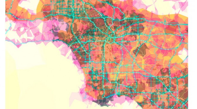
For now, let’s set our eyes West, on L.A. County. Like prettymaps (sfba), prettymaps (la) is derived from all sorts of information, from all over the internet. Its translucent layers illuminate information we’re used to relying on maps for–the green lines are OSM roads and paths, and orange marks urban areas as defined by Natural Earth. They also highlight what’s often not seen–the white areas show where people on Flickr have taken pictures. It’s an inverse of a kind of memory-making–a record of where people were looking from instead of what they were looking at, as they sought to remember a specific place and time.

Portals


I love the magically mundane virtual real world of Google Streetview, and like others I’ve longed for my 15 frames of blurry low-res Street View fame. So I’ve been wondering, how can I get into Street View without having to stalk the car and chase it down? Actually, I don’t just want to appear in Street View, I want to play in it and add things to it too. And I want to be able to invite my friends to join me on the street. I want to use Street View for more than looking at a random piece of the past. I want to use Street View as a place to make alternative presents and possible futures.

To help me fulfill this desire (and part of my thesis project), I’ve been prototyping magical portals to get into Google Street View.

I’ve also decided to launch a Kickstarter project to help take the prototype to the next level and see if other people might be interested in exploring this and other related ideas with me.


It turns out, making portals is also happens to be a good way to think about a lot of other things as well. For instance, why does the screen still feel like a glass wall between me an an interface? And how could I get around this wall in a fun and fluid way?

Lately, people have been really into using touch screens (pictures under glass) and gestures (lick a stamp!). But as cool as these things are, they still keep us on one side of the screen and the interface on the other. Not that I think we need to get rid of screens entirely and just have holograms in dark rooms every where. Screens are actually quite magical and we can take advantage of them. But what would happen if we could just make a little space for the real world between the screen and the interface?

Also, what other ways can we think about being co-present with people? There’s the completely CG virtual worlds, full of anonymity and low polygon fantasies. We also have plenty of banal desktop sharing and collaborative white boarding applications. Then there’s standard video conferencing which keeps people in their own separate boxes awkwardly avoiding eye-camera contact. And of course there’s always Real Life, but that’s bound by the rules of space and time. What if we could take a little from all these things and combine them into something that is both more real and more magical?

These are some of the things that I’ve been researching through making these portals. I’m not sure what other questions might come up as I move forward, but it’s a starting point for now.

If you’re interested in helping me explore these ideas while making these Portals, check out the Kickstarter project!

Continue reading Portals

The Week Ending 080110

Sunday September 20, 12.53.26

Markings for repair or warnings to mitigate accidents? Seen in Seoul, South Korea.

Whilst technically still on holiday, there were some things done as usual and *holiday* is never entirely just not doing nuthin’.

There was a quick visit to the studio to begin to finish the second of two commissioned Trust devices, which is looking simultaneously quite insightful and lovely. I hope some day that this becomes a lever to torque the rudder if even ever so slightly.

Jennifer Leonard’s interviews in Good Magazine’s Slow Issue (*Perspectives on a smarter, better, and slower future*) with Esther Dyson, Jamais Cascio, Bruce Sterling, John Maeda, Alexander Rose and myself appeared online. The topic of the short discussions? “We asked some of the world’s most prominent futurists to explain why slowness might be as important to the future as speed.”

And, prompted by Rhys’ clever insights into a richer, smarter less ROI-driven vector into thinking about this whole, you know..augmented reality mishegoss, I’ve been reading a fascinating history of linear perspective that has been helping guide more meaningful thinking. (I have yet to see anything that leaps much further beyond flags showing where something is by holding up a device in front of my face, which just seems momentarily cool and ultimately not particularly consonant with all the hoopleheaded hoopla.

I’ve started The Renaissance Rediscovery of Linear Perspective, which has a number of curious insights right off the bat, particularly ones that remind us that linear perspective is only a possibility and not necessarily something to be thought of as “realistic” from a variety of perspectives. In fact, it merely makes renderings that remove experience and abstract points-of-view, something that I recently learned from Latour’s Visualisation and Cognition (which, not unsurprisingly, led me to this Edgerton book via a reference and footnote.)

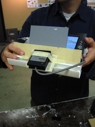
Configuration A - Binocular Form Factor

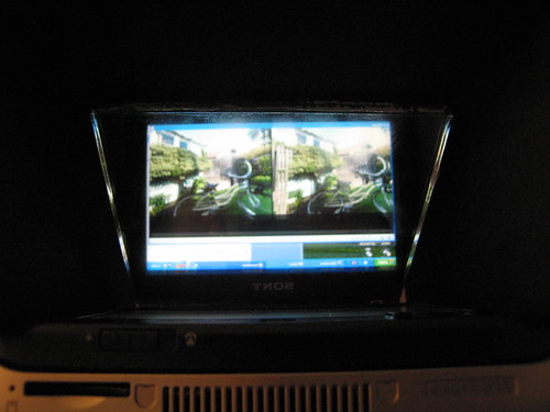
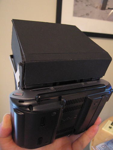
A Laboratory experiment from 2006 — *Viewmaster of the Future* — using a binocular-style form factor. ((The lenses are removed in this photo.))

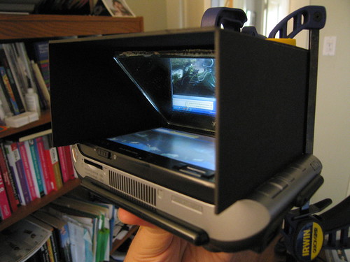
And, the follow-on, which I haven’t started yet is the enticingly titled The Mirror, the Window, and the Telescope: How Renaissance Linear Perspective Changed Our Vision of the Universe, which immediately caught my eye as I am drawn more to the history, imagery, rituals and *user experience* dimensions of telescopes and binoculars as affordances for, bleech..*augmented reality* than this stupid hold-a-screen-up-to-my-face crap. ((cf. this stuff below — the screen-up-to-my-face configuration — never felt as good as the second iteration of this *Viewmaster of the Future* experiments we did a few years ago.))

Continue reading The Week Ending 080110

Summer Backyard Laboratory Experiment: Immersive Viewer Apparatus, Configuration B

I spent a week or so wrangling some variations on the immersive viewer apparatus for the little research group at USC working on this project. Some of the “early” prototyping of the concept I had done last winter, described in this blog post.

Taking a hint from Mark Bolas to try some design prototyping with foam core and an Xacto knife, I figured I’d try some ideas out. I have to say, that after mostly thinking, writing and wrangling groups of people for conference, symposium and workshops, doing some tangible sort or craft work was incredibly satisfying. It was really nice to be in a situation where I was generating sawdust and sparks.

I managed to get a hold of one of the new Sony UX-180 UMPC form-factor devices (Windows XP, Core Solo 1.2GHz, 512MB RAM) an overpriced fetish device that, despite the cost, was perfect for this particular prototyping exercise. If an immersive viewer were to be as normal as an iPod this might be about the form-factor, i would guess. The unit is approximately the size of an unfolded Nintendo DS, and definitely heavier. The display is somewhere between good and excellent, imho, and despite the small size, the resolution of the screen only presents small challenges for reading text.

The goal of this little design and coding experiment was to create a reasonably self-contained viewer prototype that would allow form-factor and handling tests, figure out what optics configurations work (lenses, image size, etc.), have a platform for testing the omnistereo QuicktimeVR imagery and test software designs on this particular platform.

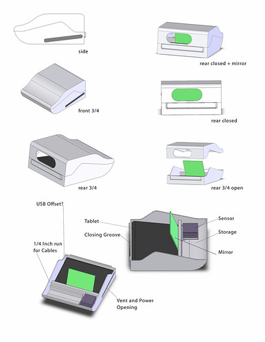
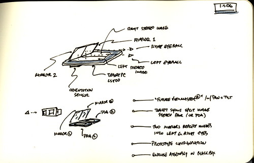
The “Configuration A” prototype used a huge TabletPC and a simple reflecting mirror system, together with a beautifully designed and humongous custom designed enclosure by the masterful Sean Thomas, a grad student at Art Center College of Design. The general idea was to orient the screen horizontally and use a mirror to increase the optical distance between one’s eyeballs and the screen by reflecting light. I was also guessing that it would be easier to hold the whole apparatus as if one were getting ready to take a bite out of a giant deli sandwich. Holding the apparatus out with one’s arms extended, quickly became tiring.

Second meeting at Art Center with Sean Thomas and Jed Berk to go over the first breadboard version Sean created. Placement of the sensor is an issue — it is sensitive to metal and EM fields generated by the TabletPC. We experimented with a few placement options, including in front, below in various places. Sean had the idea of a cut-out in the breadboard so that the sensor could go below, without sticking way out in the bottom. We foudn that th ebest placement for the time being seemed to be in the front, in front of the mirror. Sean showed me some of the 3D printing materials. We settled on this plaster material, which is more fragile than ABS, and cheaper. It seemed robust enough for a first version housing. Showed a few students who happened to be in the studio the app and they all thought it was very cool, so that’s, like..cool.

Sean had the difficult challenge of making something that would fit both a large TabletPC while still being well-designed enough to be somewhat hand-held and suitable for demonstrating the conceptual underpinnings of the project. He ulimately came up with a design that, I was told, was the biggest thing to come out of the Art Center’s 3D printer. I don’t know if that’s good or bad..

This “Configuration A” prototype was a great learning experience. Things like realizing that everything in the display is now backwards was a great part of the prototyping/learning experience. Realizing that I needed to find an expedient way to eliminate the wires that connected the sensor hardware to the computer was a great part of the prototyping/learning experience. Discovering that the Max/MSP patch I was using to broker the signals from the sensor to QuicktimeVR actually turned the QuicktimeVR in the “wrong” directin was a great part of the prototyping/learning experience.

So, “Configuration A” was an unqualified success in these regards. Definitely something that I could learn from and improve. Alas, I filed it away for several months an put the project on a semi-hold.

Then I started working on “Configuration B”, with a much smaller and much more powerful CPU, at least on paper — the Sony UX-180.

With more time this summer to work on the prototype, I decided I wanted to get rid of Max/MSP as the software “middleware” and code something from scratch. I felt I wanted to get closer to a solution that was as close to the operating system as possible, to maximize efficiencies and all the rest.

A quick test indicated that there was sufficient support within Windows .NET framework for QuicktimeVR to do what I wanted to do, and, from the specs, the UX-180’s graphics chipset was actually more robust than that on the TabletPC I had been using. Technically, it should work well, but it wasn’t until I got the UX-180 that I’d know. Of course, I delicately unpacked the unit in case I decided to return it.

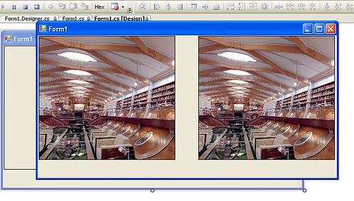
With a little test app, attempting to simultaneously render two QuicktimeVRs (left eye and right eye for the ultimate goal of stereoscopy), I found out that the little UX-180 was up to the task.

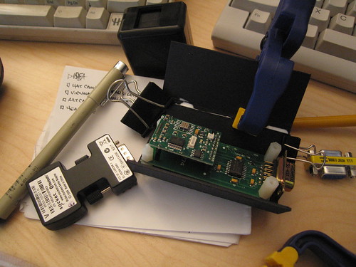
I patched in some RS232 serial protocol code to link together the sensor and the QuicktimeVRs, so that the sensor would provide the viewing point-of-view angle and booted it up on the UX-180. Although the device would render the QuicktimeVRs without any problem, I quickly found out that the UX-180, strangely, completely balked at reading the serial data with any reasonable speed. The machine literally ground to a halt, the mouse staggered and the fan spun up like a turbine. WTF? Render two video windows with no problem, but as soon as you have a little threaded serial port data reader, reading 12 bytes at a clip, the machine stalls? How disheartening. At first I thought it was my code, but even running some very simple tests straight from some trivial design patterns caused the same problem. I have been using Johan Franson’s amazing Serial Tools kit from franson.biz for years, and it was hard to believe this was the culprit. But, I went native just to eliminate the possibility and wrote my own serial port reader using the built-in .NET APIs. It worked much better, but I don’t blame Serial Tools and here’s why: everything runs fine on multiple desktop machines and the TabletPC. It’s only when the code attempts to run on the UX-180 that there are problems, leading me to believe that there is some particular weirdness on the UX-180 that causes the Serial Tools code to gum up.

So long as I could get the code to run, even using the slightly less elegant .NET “native” serial port API, I was happy. Now it was on to some physical prototyping.

I guess I had the “binocular” form factor stuck in my head from the original Sean Thomas prototype. I just immediately started creating a similar configuration from cardboard and went to my local glazer and had a bunch of tiny mirrors cut.

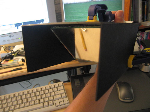
My general goal for the Binocular Form Factor was as you see below. I got fairly well into it, but once I clamped it to the UX-180 just to see how it felt, a few problems arose. First, the UX-180 had to be oriented such that the “top” of the screen (as one would view it if you were holding the device conventionally), had to be towards your face because the mirror reverses everything. No biggie, except that there is a fan there (there’s also one on the bottom, but much less significant) that seems to be the busiest of them all. Not huge, but with your chin essentially abutting it, the heat is uncomfortable, to put it mildly. I thought of putting a small deflector baffle there, but quickly the whole design seemed destined to be awkward and embarrassing.

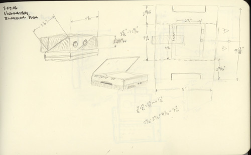
One of the problems of working alone in the back shed is that you don’t get collegial feedback and dialogue. It’s okay — that was just the circumstances of working during summer break. But had I been around others, we may have come up with an alternative — the one that struck me while I was riding my bike somewhere — what about a “periscope” style design? The UX-180 has this slide-up/slid-down screen which would make such an architecture suitable for that configuration, while also providing access to the keyboard. (One of the considerations I had was how to control various “meta” features of the viewer — switching slides, etc. Keyboard buttons and soft-switches are perfect for this.)

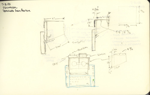
I sketched this out and then got busy with the Xacto..

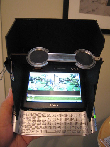
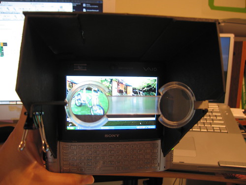
Configuration B - Periscope Form Factor

Configuration B - Periscope Form Factor


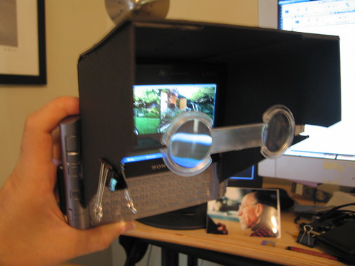
Configuration B — Periscope Form Factor

In these images you can see a design that’s much more accommodating to the general flavor of the viewer. I got a small selection of lenses designed for stereoscopy from 3D Stereo and tossed them in there, spent an evening sprucing up the viewer software, put in a simple Bluetooth-to-Serial dongle to avoid having to run a clunky USB cable into the UX-180, and processed a bunch of test 3D panoramas, turning them into QuicktimeVRs and gave it all a whirl.

The whole configuration works much better than I would’ve expected from a second prototype. I configured the soft-key “zoom-in/zoom-out” buttons on the UX-180 to move forward and backward through a directory of QuicktimeVRs. The directory either contains stereo pairs named “Right_XYZ” and “Left_XYZ” so the system knows which one’s to pair together. (Note to self: remember that the naming scheme also contains numerics indicating the size of the slit width and the distance — left or right – from the image center line that the slits are taken from so I can recollect how the image was processed and what configuration of these parameters work best to deliver decent stereo acuity.) The software consistently breaks the first time it starts up (but doesn’t after that first time), which I think means that I should not manually connect the device to the sensor before starting the software. Switching from the 3D panoramas to conventional QuicktimeVR panoramas works well in software, but, obviously, a different set of optics need to be moved in place in order to see non-stereo, non-3D renderings.

Resources
Summer Laboratory Experiment: Producing Stereo QuicktimeVRs
Consumer Immersive Viewer

Thanks
Sean Thomas
Michael Naimark
Jed Berk
Art Center Model Shop

Summer Laboratory Experiment: Producing Stereo QuicktimeVR

Left_30_380.jpg

The back story of the project tracks back to a conversation with Naimark. Working on the (wrong) impression that a stereo panorama could be created trivially, using two cameras on a rotating, panoramic rig, I was all set to make stereo QuicktimeVRs. Naimark pointed me to a research paper that indicated that such a camera configuration wouldn’t work for a panorama — the geometry is hooey when the two cameras rotate about an axis in between them if you try to capture one continuous image for the entire panorama. In other words, setting up two cameras to each do their own panorama, and then using those two panoramas as the left and right pairs will only produce stereo perception from the point of view at which the cameras are side-by-side, as if they were producing a single stereo pair. You would have to pan around, capturing an image from each point of view, and mosaic all those individual images to produce the stereo.

(I put the references to research papers I found useful — or just found — at the end of this post.)

This is the experiment I wanted to do — two cameras, capturing an image from every view point (or as many as I could) and create a mosaic from slits from every image. That’s supposed to work.

I plowed through the literature and found a description of a technique that required only one camera to create a stereo pair. That sounded pretty cool. By mosaicing a sequence of images taken from individual view points, while rotating the single camera about an axis of rotation behind the camera, you can create the source imagery necessary to create the stereo panorama. Huh.. It was intriguing enough to try. The geometry as described still hasn’t taken hold, but I figured I would play an experimentalist and just try it.

So, the project requires about three steps — the first is to capture the individual images for the panorama, and the second is to mosaic those images by cobbling together left and right slits into left and right images, the third is to turn those left and right images into Quicktime VRs.

After a couple of days poking around and doing some research, I finally decided to build my own — this would save a bunch of money and also give me some experience creating camera control platform for the backyard laboratory.
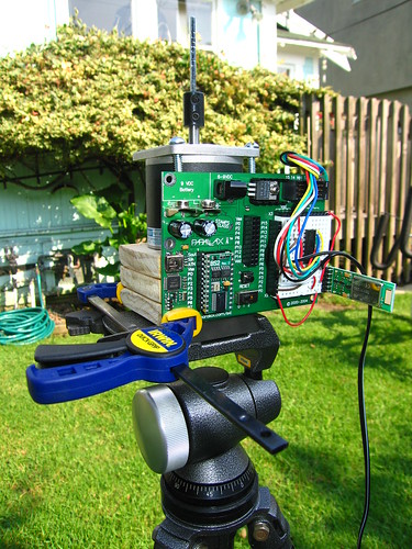
omnistereo rig

Camera Control Platform
My idea was pretty straightforward — create a rotating arm with a sliding point of attachment for a camera using a standard 1/4″ screw mount. I did a bit of googling around and found a project by Jason Babcock, an ITP students who created a small rig for doing slit-scan photography. (The project he did in collaboration with Leif Krinkle and others was helpful in getting a sense of how to approach the problem. The geometry I was trying to achieve is different, but the mechanisms are the same, essentially, so I got a good sense of what I’d need to do without wasting time making mistakes.)

While I was waiting for a few parts to arrive, I threw together a simple little controller program using a Basic Stamp 2 that could be controlled remotely over Bluetooth. I wanted to be able to step the camera arm one step at a time either clockwise or counter-clockwise just by pushing a key on my computer, as well as have it step in either direction a specific number of steps with a specific millisecond delay between each step.
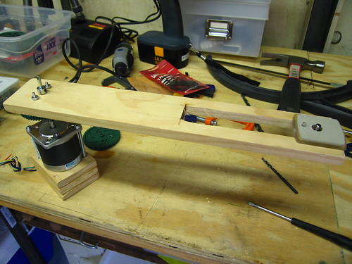
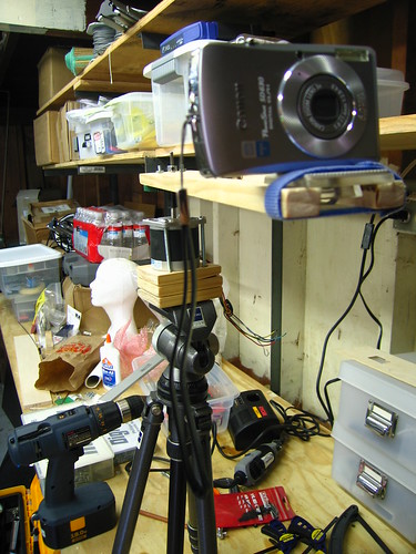
omnistereo rig

omnistereo rig

My first try was to use the rig to rotate in a partial circle, accumulate the source imagery and then figure out how I could efficiently create the mosaics. There was no clear information on the various parameters for the mosaics. The research papers I found explained the geometry but not what the “sweet spots” were, so I just started out. I positioned the camera in front of the axis of rotation and set it up in the backyard. I captured about 37 images in maybe 60 degrees. At each step of 1.8 degrees, I captured an image using an IR remote for my camera.

There were any number of problems with the experiment, and I was pretty much convinced that there was little chance this would work. The tripod wasn’t leveled. There was all kinds of wobble in the panorama rig. The arm I was using to position the camera in front of the axis of rotation had the bounce of a diving board. Etc., etc. Plus, I wasn’t entirely sure I had the geometry right, even after an email or two back and forth with Professor Shmuel Peleg, the author of many of the papers I was working from.
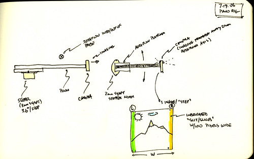
Panorama Table Sketch

Image Mosaics
With 37 source images, I had no clear idea about how to post-process them. I knew that I had to interleave the mosaics, taking a portion from left of the center for the right eye view, and a portion from right of the center for the left eye view. Reluctantly, I resorted to Apple Script to just the job done — scripting the Finder and Photoshop to process images in a directory appropriately. I added a few parameters that I could adjust — left and right (obviously), the “disparity” — number of pixels from the center where the mosaic slit should be taken, and width of the slit. I plugged in a few numbers — 40 pixels for the disparity and a slit width of 30 and just let the thing run, and this is what I got for the right eye.
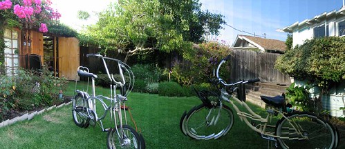
Right_30_260.jpg

You can see each slit produces a strip in the final image. It’s most obvious because of exposure differences or disjoint visual geometry. (Parenthetically, I made a small change to the Apple Script to save each individual strip and then tried using the panorama photo stitcher that came with my camera on those strips — it comlained that it had a minimum photo size of 200 pixels or something like that. I also tried running it on some other, more prosumer photo stitcher, but I got tired of trying to make sense of how to use it.)

With the corresponding left eye image (same parameters), I got a stereo image that was wonky, but promising.

Here are the arranged images.
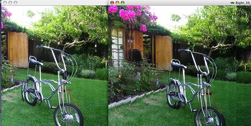
BackyardPanorma_1_L380_R260_30

I did a few more panoramas to experiment with, well..just to play with what I could do. Now I had the basic tool chain figured out except for the production of a QuicktimeVR from the panoramas. After trying a few programs found a program called Pano2QTVR (!) that can produce a QuicktimeVR from a panoramic image, so that pretty much took care of that problem — now I had two QuicktimeVRs, one for my left eyeball, the other for the right.

Why do I blog this? I wanted to capture a bunch of the work that went into the project so I’d remember what I did and how to do it again, just in case.

Materials

Tools: Dremel, hacksaw, coping saw, power drill, miscellaneous handtools and clamps, Applescript, Photoshop, BasicStamp 2, Elmer’s Glueall, tripod, Bluetooth
Parts: Stepper Motor Jameco Part No. 162026 (12V, 6000 g-cm holding torque, 4 phase, 1.8 deg step angle), Basic Stamp 2, Blue SMiRF module, Gears & Mechanicals, Mechanicals and Couplings, electronics miscellany
Time Committed: 2 days gluing, hammering, drilling, hunting hardware stores and McMaster catalog, zealously over-Dremeling, ordering weird supplies and parts, and programming the computer. Equal time puzzling over research papers and geometry equations while waiting for glue to dry and parts to arrive.


References

Tom Igoe's stepper motor information page (very informative, as are most of Tom's resources on his site. Bookmark this one but good!)

S. Peleg and M. Ben-Ezra, "Stereo panorama with a single camera," in Proc. Computer Vision and Pattern Recognition Conf., pp. 395--401, 1999. http://citeseer.ist.psu.edu/peleg99stereo.html

S. Peleg, Y. Pritch, and M. Ben-Ezra. Cameras for stereo panoramic imaging. In IEEE Conference on Computer Vision and Pattern Recognition (CVPR'00), Hilton Head, South Carolina, volume 1, pages 208--214, June 2000. http://citeseer.ist.psu.edu/peleg00cameras.html


P. Peer and F. Solina:"Mosaic-based panoramic depth imaging with a single standard camera, " Proc. Workshop on Stereo and Multi-Baseline Vision, pp.75-84, 2001 http://citeseer.ist.psu.edu/peer01mosaicbased.html


Yael Pritch , Moshe Ben Ezra , Shmuel Peleg. Optics for OmniStereo Imaging, L.S. Davis (Editor), Foundations of Image Understanding, Kluwer Academic, pp. 447-467, July 2001.


Ho-Chao Huang , Yi-Ping Hung, Panoramic stereo imaging system with automatic disparity warping and seaming, Graphical Models and Image Processing, v.60 n.3, p.196-208, May 1998

Ho-Chao Huang and Yi-Ping Hung, SPISY: The Stereo Panoramic Imaging System, http://citeseer.ist.psu.edu/115716.html

 
Thanks

Professor Tom Igoe
Leif Krinkle
Jason Babcock
Professor Shmuel Peleg

 
Panotable Stitcher Program

set inputFolder to choose folder
set slitWidth to 50
set eyeBall to “Left”
set slitCornerBounds to 280
set tempFolderName to eyeBall & ” Output”
set disparity to 0
tell application “Finder”
–log (“Hey There”)
set filesList to files in inputFolder
if (not (exists folder ((inputFolder as string) & tempFolderName))) then
set outputFolder to make new folder at inputFolder with properties {name:tempFolderName}
else
set outputFolder to folder ((inputFolder as string) & tempFolderName)
end if
end tell
tell application “Adobe Photoshop CS2”
set display dialogs to never
close every document saving no
make new document with properties {width:slitWidth * (length of filesList) as pixels, height:480 as pixels}
set panorama to current document
end tell
set fileIndex to 0
–repeat with aFile in filesList by -1
repeat with i from 1 to (count filesList) by 1
–repeat with i from (count filesList) to 1 by -1
set aFile to contents of item i of filesList
tell application “Finder”
— The step below is important because the ‘aFile’ reference as returned by
— Finder associates the file with Finder and not Photoshop. By converting
— the reference below ‘as alias’, the reference used by ‘open’ will be
— correctly handled by Photoshop rather than Finder.
set theFile to aFile as alias
set theFileName to name of theFile
end tell
tell application “Adobe Photoshop CS2”
–make new document with properties {width:40 * 37 as pixels, height:480 as pixels}
open theFile
set sourceImage to current document
— Select the left half of the document. Selections bounds are always expressed
— in pixels, so a conversion of the document’s width and height values is needed if the
— default ruler units is other than pixels. The statements below would
— work consistently regardless of the current ruler unit setting.
–set xL to ((width of doc as pixels) as real)
set xL to slitWidth
set yL to (height of sourceImage as pixels) as real
select current document region {{slitCornerBounds, 0}, {slitCornerBounds + xL, 0}, {slitCornerBounds + xL, yL}, {slitCornerBounds, yL}}
set sourceWidth to width of sourceImage
set disparity to ((sourceWidth / 2) – slitCornerBounds)
if (disparity < 0) then
set disparity to ((disparity * -1) as integer)
end if
activate
copy selection of current document
activate
set current document to panorama
–select current document region {{0, 0}, {20, 480}}
make new art layer in current document with properties {name:"L1"}
paste true
set current layer of current document to layer "L1" of current document
set layerBounds to bounds of layer "L1" of current document
–log {item 1 of layerBounds as pixels}
–log {"—————-", length of filesList}
–this one should be used if the panorama was created CW
–set aWidth to ((width of panorama) / 2) – ((slitWidth * (length of filesList) + (-1 * slitWidth * (1 + fileIndex))) / 2)
— this one should be used if the panorama was created CCW
set aWidth to ((slitWidth * (length of filesList) + (-1 * slitWidth * (1 + fileIndex))) / 2)
translate current layer of current document delta x aWidth as pixels
–set sourceName to name of sourceImage
–set sourceBaseName to getBaseName(sourceName) of me
set fileIndex to fileIndex + 1
–set newFileName to (outputFolder as string) & sourceBaseName & "_Left"
–save panorama in file newFileName as JPEG appending lowercase extension with copying
close sourceImage without saving
flatten panorama
–set disparity to (sourceWidth – slitCornerBounds)
–if (disparity < 0) then
— disparity = disparity * -1
–end if
— this'll save individual strips
make new document with properties {width:slitWidth as pixels, height:480 as pixels}
paste
set singleStripFileName to (outputFolder as string) & eyeBall & "_" & (slitWidth as string) & "_" & (disparity as string) & "_" & fileIndex & ".jpg"
save current document in file singleStripFileName as JPEG appending lowercase extension
close current document without saving
–close panorama without saving
end tell
set fileIndex to fileIndex + 1
end repeat
tell application "Adobe Photoshop CS2"
— this saves the final output
set newFileName to (outputFolder as string) & eyeBall & "_" & (slitWidth as string) & "_" & ((disparity) as string) & ".jpg"
set current document to panorama
save panorama in file newFileName as JPEG appending lowercase extension
end tell
— Returns the document name without extension (if present)
on getBaseName(fName)
set baseName to fName
repeat with idx from 1 to (length of fName)
if (item idx of fName = ".") then
set baseName to (items 1 thru (idx – 1) of fName) as string
exit repeat
end if
end repeat
return baseName
end getBaseName

 
Stepper Motor Program

‘Stepper Motor Control
‘ {$STAMP BS2}
‘ {$PBASIC 2.5}
SO PIN 1 ‘ serial output
FC PIN 0 ‘ flow control pin
SI PIN 2
#SELECT $STAMP
#CASE BS2, BS2E, BS2PE
T1200 CON 813
T2400 CON 396
Baud48 CON 188
T9600 CON 84
T19K2 CON 32
T38K4 CON 6
#CASE BS2SX, BS2P
T1200 CON 2063
T2400 CON 1021
T9600 CON 240
T19K2 CON 110
T38K4 CON 45
#CASE BS2PX
T1200 CON 3313
T2400 CON 1646
T9600 CON 396
T19K2 CON 188
T38K4 CON 84
#ENDSELECT
Inverted CON $4000
Open CON $8000
Baud CON Baud48
letter VAR Byte
noOfSteps VAR Byte
X VAR Byte
pauseMillis VAR Word
CoilsA VAR OUTB ‘ output to motor (pin 4,5,6,7)
sAddrA VAR Byte ‘ EE address of step data for the motor
Step1 DATA %1010
Step2 DATA %0110
Step3 DATA %0101
Step4 DATA %1000
Counter VAR Word ‘ count how many steps, modulo 200
DIRB = %1111 ‘ make pins 4,5,6,7 all outputs
sAddrA = 0
DEBUG “sAddr is “, HEX4 ? sAddrA, CR
Main:
DO
DEBUG “*_”
‘DEBUG SDEC4 Counter // 200, ” “, HEX4 Counter, ” “, BIN16 Counter, CR
SEROUT SOFC, Baud, [SDEC4 ((Counter)*18), ” deg x10 “]
SEROUT SOFC, Baud, [CR, LF, “*_”]
SERIN SIFC, Baud, [letter]
DEBUG ” received [“,letter,”] “, CR, LF
SEROUT SOFC, Baud, [” received [“,letter,”] “, CR, LF]
IF(letter = “f”) THEN GOSUB Step_Fwd
IF(letter = “b”) THEN GOSUB Step_Bwd
IF(letter = “s”) THEN GOSUB Cont_Fwd_Mode
IF(letter = “a”) THEN GOSUB Cont_Bwd_Mode
IF(letter = “h”) THEN
DEBUG “f – fwd one step, then pause”, CR, LF,
“b – bwd one step, then pause”, CR, LF,
“sN – fwd continuous for N steps”, CR, LF,
“aN – bwd continuous for N steps”, CR, LF
SEROUT SOFC, Baud, [“f – fwd one step, then pause”, CR, LF,
“b – bwd one step, then pause”, CR, LF,
“sN – fwd continuous for N steps”, CR, LF,
“aN – bwd continuous for N steps”, CR, LF]
ENDIF
LOOP
Cont_Fwd_Mode:
SERIN SIFC, Baud, [DEC noOfSteps, WAIT(” “), DEC pauseMillis]
DEBUG ” fwd for [“, DEC ? noOfSteps, “] steps [“, DEC pauseMillis, “] pause “, CR
SEROUT SOFC, Baud, [CR, LF, ” fwd for [“, DEC noOfSTeps, “] steps [“, DEC pauseMillis, “] pause “, CR, LF]
FOR X = 1 TO noOfSteps
GOSUB Step_Fwd
PAUSE pauseMillis
NEXT
RETURN
Cont_Bwd_Mode:
SERIN SIFC, Baud, [DEC noOfSteps, WAIT(” “), DEC pauseMillis]
DEBUG ” fwd for [“, DEC ? noOfSteps, “] steps [“, DEC pauseMillis, “] pause “, CR
SEROUT SOFC, Baud, [CR, LF, ” fwd for [“, DEC noOfSTeps, “] steps [“, DEC pauseMillis, “] pause “, CR, LF]
FOR X = 1 TO noOfSteps
GOSUB Step_Bwd
PAUSE pauseMillis
NEXT
RETURN
Step_Fwd:
‘DEBUG HEX4 ? sAddrA
sAddrA = sAddrA + 1 // 4
READ (Step1 + sAddrA), CoilsA ‘output step data
Counter = Counter + 1
DEBUG ” “, BIN4 ? CoilsA, ” “, HEX4 ? sAddrA
RETURN
Step_Bwd:
sAddrA = sAddrA – 1 // 4
READ (Step1 + sAddrA), CoilsA
DEBUG “bwd “, BIN4 ? CoilsA
Counter = Counter – 1
RETURN
Viewmaster of the Future

Configuration A - Binocular Form Factor

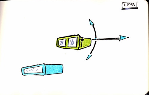
I started experimenting this summer with using orientation sensing as part of the interaction syntax for some kind of near-future cinematic interface. The idea is that your mobile device like a window into a panoramic visual story world. This is a prototype of Naimark’s Viewmaster of the future idea, in many ways. I think it’ll require some alternative rigging, perhaps an angled mirror so that the display (a TabletPC, just as a prototype — obviously too heavy, even the small 8.4″ display unit) is horizontal and the mirror reflects the image into your eyes. And, of course, stereo/3D video..and how do you create that? With the right eyepoint nodes so that stereo is maintained in a panorama?

Technorati Tags:


Continue reading Viewmaster of the Future